Tank body internal welding system

A welding system and tank technology, applied in welding equipment, welding accessories, welding rod characteristics, etc., can solve the problems of high technical requirements of welders, difficult to guarantee welding quality, and low welding productivity.

Pending Publication Date: 2021-02-23
CHINA UNIV OF PETROLEUM (EAST CHINA) +1
View PDF0 Cites 0 Cited by
  • Summary
  • Abstract
  • Description
  • Claims
  • Application Information

AI Technical Summary

Problems solved by technology

[0005] The purpose of the present invention is to provide a tank internal welding system to solve the problems of the current "small hole blind welding"

Method used


Image

  • Tank body internal welding system
  • Tank body internal welding system
  • Tank body internal welding system

Examples


specific Embodiment approach 1

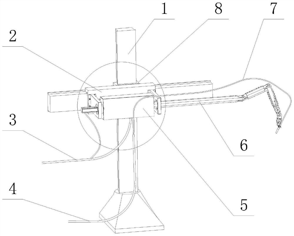
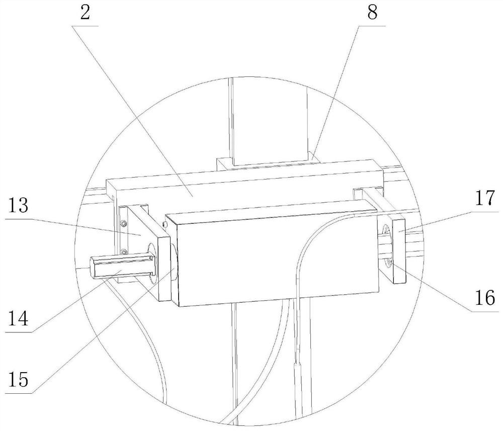
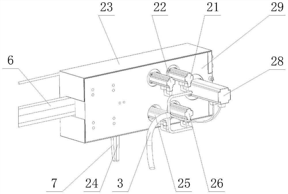
[0027] Specific implementation mode one: combine Figure 1 to Figure 15 Describe this embodiment, including cross movement platform 1, driving device 5, mechanical arm 6, servo cable 3 and welding cable 4, it is characterized in that: described mechanical arm 6 is made up of connecting rod one 60, joint two 61, connecting rod two 62, joint three 63, connecting rod three 64, joint four 65, connecting rod four 66, joint five 67, connecting rod five 68, joint six 69, the cross beam slider 2 is installed on the cross motion platform 1, the The left support 13 of the mechanical arm and the right support 17 of the mechanical arm are installed on the beam slider 2, the left support 13 of the mechanical arm is equipped with a joint-harmonic speed reducer 15, and the drive unit 5 is composed of a drive unit base 29, a drive unit The protective case 23 and 5 sets of power output systems are composed, the drive device base 29 is equipped with a left mechanical arm fixing clip 32 and a ri...

specific Embodiment approach 2

[0028] Specific implementation mode two: combination Figure 1 to Figure 15 Describe this embodiment, joint two 61 of this embodiment is composed of joint two cross roller bearing 90, joint two driven wheel 95, joint three steel wire rope guide wheel 94, joint four steel wire rope guide wheel one 92, joint five steel wire rope guide wheel One 91, joint six steel wire rope guide wire wheel one 93, connecting rod one bearing mounting flange 82, connecting rod two bearing mounting flange one 87, the connecting rod one bearing mounting flange 82 is installed on the connecting rod one 60, The joint two cross roller bearing 90 is installed on the connecting rod first bearing mounting flange 82, the connecting rod two bearing mounting flange one 87 is installed on the inner ring of the joint two cross roller bearing 90, and the connecting rod two Bearing mounting flange 1 87 is installed on connecting rod 2 62, said connecting rod 2 bearing mounting flange 1 87 is fixedly equipped wi...

specific Embodiment approach 3

[0033] Specific implementation mode three: combination Figure 1 to Figure 15 Describe this embodiment, the driving mechanism of joint two 61 in this embodiment is composed of joint two servo motor 28, joint two harmonic reducer 40, joint two driving wheel 41, joint two driven wheel 95, and joint two servo motor 28 Installed on the rear side of the driving device base 29, the output shaft of the second joint servo motor 28 passes through the driving device base 29 and is fixedly connected to the input shaft of the joint second harmonic reducer 40, and the joint second driving wheel 41 is fixedly installed on the joint second harmonic On the output shaft of reducer 40.

[0034] The driving mechanism of the joint three 63 is composed of the joint three servo motor 26, the joint three harmonic reducer 44, the joint three driving wheel 43, the transmission wheel group one 49, the joint three steel wire rope guide wheel 94, and the joint three driven wheel 108. The transmission wh...


PUM


Abstract

The invention relates to the technical field of welding equipment, and particularly relates to a tank body internal welding system. The tank body internal welding system comprises a cross motion platform, a driving device and a mechanical arm, wherein the mechanical arm is fixed on the driving device through a mechanical arm fixed hoop; a cross beam slide block is mounted on the cross motion platform; a mechanical arm left bracket and a mechanical arm right bracket are mounted on the cross beam slide block; a joint harmonic speed reducer is mounted on the mechanical arm left bracket; the driving device is mounted on an output shaft of the joint harmonic speed reducer; a mechanical arm deep groove ball bearing is mounted on the mechanical arm right bracket; the mechanical arm is mounted inthe mechanical arm deep groove ball bearing; a consumable electrode gas protection welding gun is mounted at the tail end of the mechanical arm; a harmonic speed reducer is mounted in the driving device; and an output shaft of the harmonic speed reducer drives a mechanical arm joint to move through a steel wire rope. The tank body internal welding system adopts the steel wire rope to drive the joint based on a traditional welding robot, reduces the radial size of the mechanical arm, and achieves the beneficial effects.

Description

technical field [0001] The invention relates to the technical field of welding equipment, in particular to a tank internal welding system. Background technique [0002] In recent years, my country's petroleum refining, petrochemical, coal chemical, salt chemical, nuclear power and other process industries have developed rapidly, and the number of pressure vessels has increased significantly. Pressure vessels are special equipment, and the working environment is harsh. Once failure occurs, it will cause serious personal and property losses. In the development of petrochemical enterprises, there may be defects such as cracks and surface corrosion inside the pressure vessels that have been used for a long time. The repair of these defects has attracted more and more attention. [0003] However, due to the limitation of welding conditions in the repairing process of pressure vessels, the line of sight at the root of the weld seam is blocked, and the whole picture of the weld se...

Claims


Application Information

Patent Timeline
IPC IPC(8): B23K9/173B23K9/133B23K9/28B23K9/32B23K101/12
CPCB23K9/133B23K9/173B23K9/28B23K9/32B23K2101/12Y02P70/10
Inventor 冯涛段琼
Owner CHINA UNIV OF PETROLEUM (EAST CHINA)
Why Eureka
Try Eureka