An all-fiber laser detection system and working method for tunnel safety monitoring
A safety monitoring and laser detection technology, applied in measurement devices, optical devices, color/spectral characteristic measurement, etc., can solve problems such as low work efficiency, poor real-time performance, and low detection accuracy, and achieve high accuracy, high sensitivity, The effect of the simple structure of the device
- Summary
- Abstract
- Description
- Claims
- Application Information
AI Technical Summary
Problems solved by technology
Method used
Image
Examples
Embodiment 1
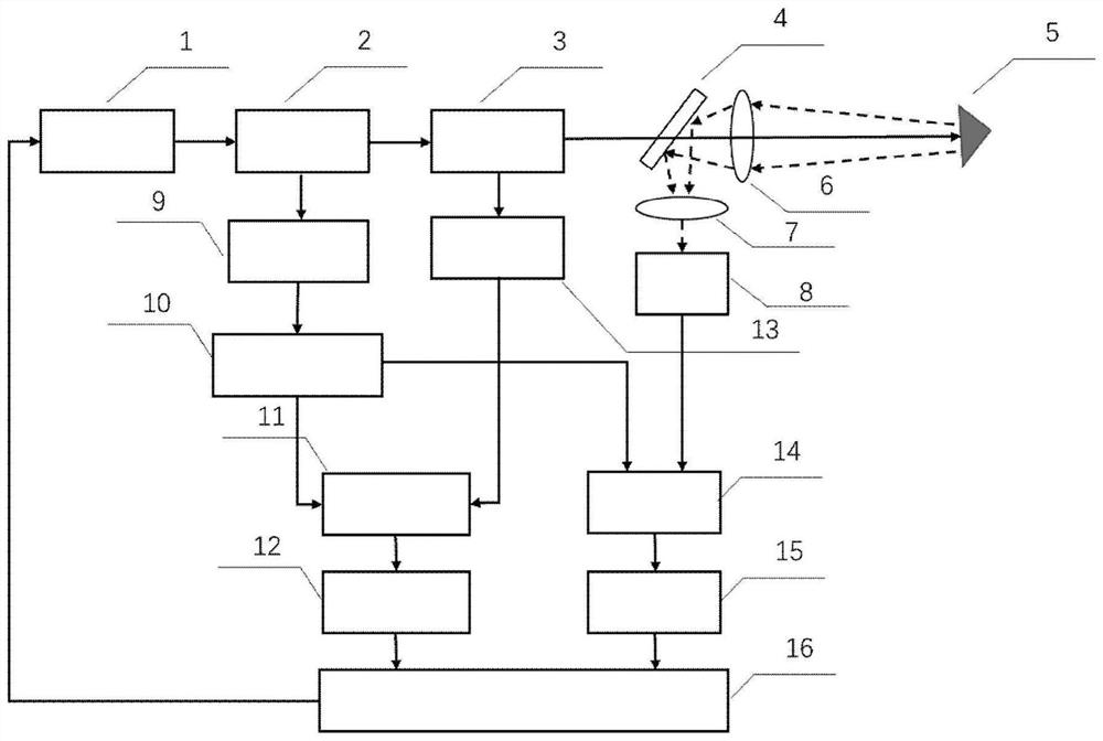
[0034] An all-fiber laser detection system for tunnel safety monitoring, including a laser, an optical fiber splitter 1 is arranged on the output optical path of the laser, and the two outputs of the optical fiber splitter 1 are respectively sent to the optical fiber splitter 2 and the fiber modulator, and the fiber modulation The output of the splitter is connected to the fiber splitter 3.
[0035] The two outputs of the fiber splitter 3 are respectively connected to the fiber combiner 1 and the fiber combiner 2 .
[0036] One output of the fiber splitter 2 is connected to the fiber combiner 1 through the fiber circulator, and the other output of the fiber splitter 2 is reflected by the mirror, then connected to the fiber combiner 2 through an aspheric lens and a fiber coupling head .
[0037] The optical fiber combiner 1 is connected to the data acquisition processing and control system through the photodetector 1 , and the optical fiber combiner 2 is connected to the data ...
Embodiment 2
[0039] An all-fiber laser detection system for tunnel safety monitoring, its structure is as described in Embodiment 1, the difference is that the optical fiber beam splitter 1 is a 90 / 10 optical fiber beam splitter, and the laser is split by the 90 / 10 optical fiber beam splitter It is the A path with 90% energy and the B path with 10% energy, and the A path is input to the optical fiber splitter 2 .
[0040] The optical fiber beam splitter 2 is a 90 / 10 optical fiber beam splitter, and the A-path laser is then divided into the E-path with 90% energy and the F-path with 10% energy through the 90 / 10 optical fiber beam splitter 2.
[0041] The optical fiber beam splitter 3 is a 45 / 55 optical fiber beam splitter. After passing through the optical fiber modulator, the B-path laser is divided into the C path with 45% energy and the D path with 55% energy through the 45 / 55 optical fiber beam splitter 3.
[0042] The E-path laser is reflected by the mirror, coupled by the aspheric len...
Embodiment 3
[0047]An all-fiber laser detection system for tunnel safety monitoring, its structure is as described in Embodiment 2, the difference is that the data acquisition processing and control system generates a modulation signal to drive the laser.
[0048] The modulation signal is a triangular wave signal, and the wavelength period of the modulation signal is T, T=T1+T2+T3; at the time 0-T1, the sine signal and the rise time triangular wave signal are used to measure the water vapor, and at the time T1-T2, the sine wave is used Signal and rising time triangular wave signal to realize methane measurement; at T2-T3 time, use falling time triangular wave signal to realize displacement and deformation monitoring of the system.
PUM
| Property | Measurement | Unit |
|---|---|---|
| wavelength | aaaaa | aaaaa |
Abstract
Description
Claims
Application Information
 - R&D
- Intellectual Property
- Life Sciences
- Materials
- Tech Scout
- Unparalleled Data Quality
- Higher Quality Content
- 60% Fewer Hallucinations
Browse by: Latest US Patents, China's latest patents, Technical Efficacy Thesaurus, Application Domain, Technology Topic, Popular Technical Reports.
© 2025 PatSnap. All rights reserved.Legal|Privacy policy|Modern Slavery Act Transparency Statement|Sitemap|About US| Contact US: help@patsnap.com

