
Inverter and power grid complementary motor power supply device and method thereof

A power supply device and inverter technology, applied in circuit devices, output power conversion devices, electrical components, etc., can solve the problems affecting the normal operation of the motor, not cost and economy, inverter overcurrent, etc., to achieve transition The effect of slow process, small number of switches and simple circuit structure

Inactive Publication Date: 2021-03-02
NANJING VOCATIONAL UNIV OF IND TECH
View PDF0 Cites 0 Cited by
  • Summary
  • Abstract
  • Description
  • Claims
  • Application Information

AI Technical Summary

Problems solved by technology

Forming a complementary power supply form between the inverter and the grid helps to improve the reliability of the motor operation and the economy of the system. The existing method of complementary power supply between the inverter and the grid usually only considers that one inverter corresponds to one motor. method, this "one-to-one" complementary power supply method is not the best in cost and economy. At the same time, the inverter and the grid power supply device add a reactor between the inverter and the grid. By locking the phase of the grid, the switching time The output voltage amplitude and phase of the power grid and the inverter are consistent, and the output of the inverter is cut off after the same frequency and phase. This control method uses reactor filtering. The output voltage contains a large number of harmonic voltages. After the harmonic voltage passes through the reactor, a large harmonic current is poured into the grid, which may cause problems such as inverter overcurrent.
To suppress the harmonic current, a reactor with a large inductance is required, which will cause a large voltage drop on the reactor when the inverter starts the motor, which will affect the normal operation of the motor, and the practicability is poor.

Method used

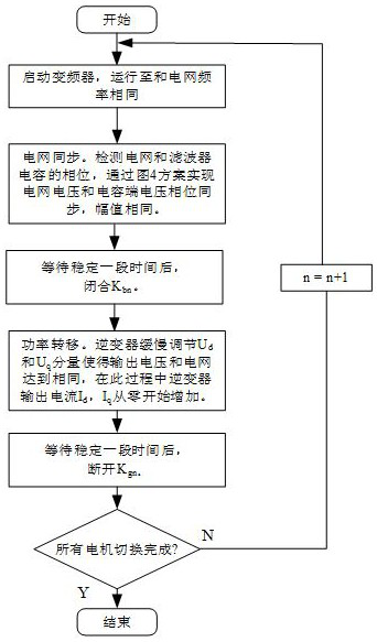
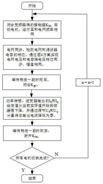

Image

  • Inverter and power grid complementary motor power supply device and method thereof
  • Inverter and power grid complementary motor power supply device and method thereof
  • Inverter and power grid complementary motor power supply device and method thereof

Examples


Embodiment Construction

[0026] In order to make the technical means, creative features, goals and effects achieved by the present invention easy to understand, the present invention will be further described below in conjunction with specific embodiments.

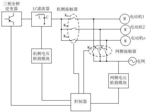
[0027] Such as figure 1 As shown, a motor power supply device in which the inverter and the power grid are complementary includes a three-phase full-bridge inverter, an LC filter, a motor, a power grid and a controller, and the three-phase full-bridge inverter is connected to the LC filter, The motor is connected to the LC filter through the machine-side contactor, and the motor is also connected to the power grid through the grid-side contactor. The output terminal of the LC filter is connected to the machine-side voltage detection module to detect the voltage across the capacitor in the LC filter. The power grid The output terminal is connected to the grid-side voltage detection module to detect the grid voltage. The controller is connected to t...


PUM


Abstract

The invention discloses an inverter and power grid complementary motor power supply device and a method thereof, and relates to the technical field of motor power supply devices and methods thereof, the device comprises a three-phase full-bridge inverter, an LC filter, a motor, a power grid and a controller, the power supply method comprises inverter power supply conversion to power grid power supply control and power grid power supply conversion to inverter power supply control, V / F control is adopted before inverter switching, the control method is simple, switching of any number of motors is achieved, expandability is high, the cost is reduced, the transition process of inverter and power grid complementary power supply switching is slow, no current or mechanical impact is caused to themotor and the power grid, flexible switching is achieved, the circuit structure is simple, and the number of switches is small.

Description

technical field [0001] The invention relates to the technical field of a motor power supply device and a method thereof, in particular to a motor power supply device and a method thereof in which an inverter and a power grid are complementary. Background technique [0002] With the development of power electronics technology, computer technology and control technology, the motor is powered by an inverter because of its advantages of simple speed regulation and good control performance, and its application fields are becoming more and more extensive. In some occasions with constant speed drive and low torque requirements, the method of grid direct drive motor still has great advantages. First, the grid direct drive saves the high cost of the inverter. Low loss and relatively high efficiency. Forming a complementary power supply form between the inverter and the grid helps to improve the reliability of the motor operation and the economy of the system. The existing method of ...

Claims


Application Information

Patent Timeline
Patent Type & Authority Applications(China)
IPC IPC(8): H02J9/06H02M1/12
CPCH02J9/062H02M1/126H02J9/068
Inventor 丁强倪拓成汪莹旭
Owner NANJING VOCATIONAL UNIV OF IND TECH
Learn More