Additive and subtractive composite manufacturing process equipment

A manufacturing process, adding and subtracting material technology, applied in the field of adding and subtracting materials composite manufacturing process equipment, can solve the problems of large amount of material removal, use of a large amount of cutting fluid, precision error and time cost, etc., to expand the range of movement and reduce equipment costs , The effect of reducing the height of the equipment

Active Publication Date: 2021-03-05
SHENYANG INST OF AUTOMATION - CHINESE ACAD OF SCI
View PDF6 Cites 4 Cited by
  • Summary
  • Abstract
  • Description
  • Claims
  • Application Information

AI Technical Summary

Problems solved by technology

Taking mold parts with internal cooling channels as an example, not only must the shape accuracy of the cavity and flow channels be guaranteed, but also high requirements are placed on the surface quality of the mold cavity and flow channels. The traditional manufacturing method is For milling of the entire blank, the complex cavity is generally processed by a five-axis machine tool, which has high equipment costs, a large amount of material removal, and a large amount of cutting fluid is used during the processing, which is not conducive to environmental protection. Another manufacturing method is to use Additive manufacturing methods, such as laser selective melting (SLM), melt metal powder layer by layer in selected areas. The shape accuracy of parts manufactured by laser selective melting can be as high as 0.1mm, but the surface roughness is not ideal. Mold parts manufactured by this method often require post-processing such as milling and polishing on specific surfaces, and the parts need to be clamped again, resulting in accuracy errors and time costs

Method used


Image

  • Additive and subtractive composite manufacturing process equipment
  • Additive and subtractive composite manufacturing process equipment
  • Additive and subtractive composite manufacturing process equipment

Examples


Embodiment Construction

[0035] The present invention will be described in further detail below in conjunction with the accompanying drawings.

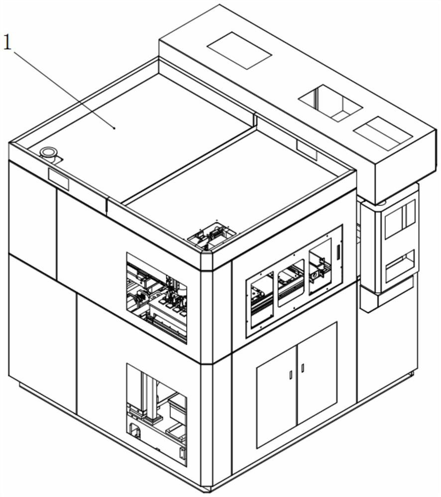
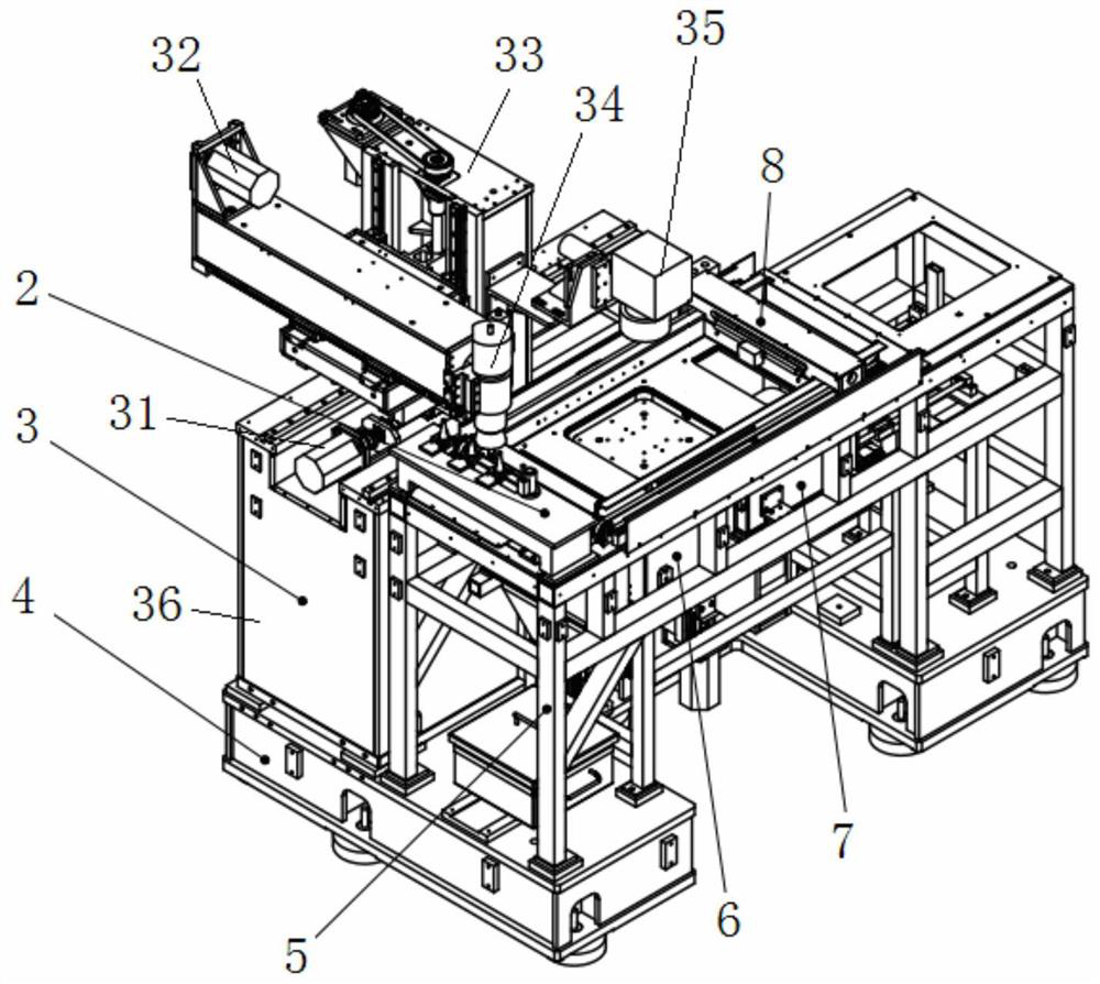
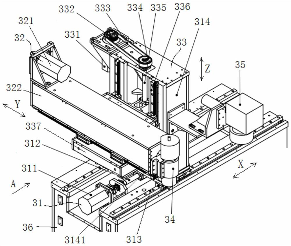
[0036] Such as Figure 1-13 As shown, the present invention includes a protective cover 1, a material reducing device 3 and a bracket 5, the material reducing device 3 and the bracket 5 are arranged in parallel in the protective cover 1, and the material reducing device 3 is provided with an electric spindle with three degrees of freedom of XYZ 34 and a laser vibrating mirror 35 with an X degree of freedom, the support 5 is provided with a powder spreading device 8, a powder supply box 7 and a forming box 6, wherein as Figure 5 As shown, the powder spreading device 8 is provided with a powder spreading panel 807 and a movable scraper 810, and the powder spreading panel 807 is provided with a powder supply port 813 and a forming port 815, and the powder supply box 7 is located at the bottom side of the powder supply port 813, And if Figure 8 As shown, the ...


PUM


Abstract

The invention relates to the technical field of precision machine manufacturing, in particular to additive and subtractive composite manufacturing process equipment which comprises a protective cover,a subtractive device and a support. The subtractive device and the support are arranged in the protective cover, and the subtractive device is provided with an electric spindle with X, Y and Z degrees of freedom and a laser galvanometer with X degrees of freedom. A powder spreading device, a powder supply box and a forming box are arranged on the support, the powder spreading device is provided with a powder spreading panel and a movable scraper, a powder supply port and a forming port are formed in the powder spreading panel, the powder supply box is arranged on the lower side of the powdersupply port, a liftable powder supply piston is arranged in the powder supply box, and the forming box is arranged on the lower side of the forming port. A liftable forming piston is arranged in the forming box, a powder supply moving mechanism is arranged in the support, and the powder supply box is driven by the powder supply moving mechanism to move between the powder supply port and a powder supplementing port. The equipment is reasonable in space layout, good in sealing performance, accurate in powder supply and capable of achieving online detection, the machining quality and precision are guaranteed, and the machining efficiency is improved.

Description

technical field [0001] The invention relates to the technical field of precision machinery manufacturing, in particular to a compound manufacturing process equipment of adding and subtracting materials. Background technique [0002] The precision manufacturing of complex parts is an urgent problem to be solved in my country's aviation, aerospace, precision mold and other industries. Taking mold parts with internal cooling channels as an example, not only must the shape accuracy of the cavity and flow channels be guaranteed, but also high requirements are placed on the surface quality of the mold cavity and flow channels. The traditional manufacturing method is For milling of the entire blank, the complex cavity is generally processed by a five-axis machine tool, which has high equipment costs, a large amount of material removal, and a large amount of cutting fluid is used during the processing, which is not conducive to environmental protection. Another manufacturing method ...

Claims


Application Information

Patent Timeline
Patent Type & Authority Applications(China)
IPC IPC(8): B23P23/04B33Y30/00B33Y40/00
CPCB23P23/04B33Y30/00B33Y40/00
Inventor 唐成铭赵吉宾赵宇辉田同同李春昱
Owner SHENYANG INST OF AUTOMATION - CHINESE ACAD OF SCI
Why Eureka
Try Eureka