
A composite material hole processing pcd drilling and milling chamfering tool

A composite material and chamfering tool technology, which is applied in milling cutters, manufacturing tools, drilling accessories, etc., can solve problems such as poor shock absorption effect, and achieve the effects of avoiding drill bit damage, improving surface roughness, and maintaining precision

Active Publication Date: 2021-08-06
河源市蓝海米克模具刀具有限公司
View PDF5 Cites 0 Cited by
  • Summary
  • Abstract
  • Description
  • Claims
  • Application Information

AI Technical Summary

Problems solved by technology

[0005] For this reason, the present invention provides a PCD drilling and milling chamfering tool for composite material hole processing. The polycrystalline diamond blade is welded through the inner wall of the installation groove, and the limiting post of the cutting head is inserted into the through hole at the bottom of the drill rod. At the same time, one side of the cutting head and The limit groove 1 is connected, the protrusion of the drill pipe is inserted into the limit groove 2 of the cutting head, so that the groove 2 is perpendicular to the axis of the threaded hole, the screw is inserted into the inner wall of the through hole through the threaded hole, and fixed with the groove 2 of the limit column, To solve the problem of poor shock absorption

Method used


Image

  • A composite material hole processing pcd drilling and milling chamfering tool
  • A composite material hole processing pcd drilling and milling chamfering tool
  • A composite material hole processing pcd drilling and milling chamfering tool

Examples


Embodiment 1

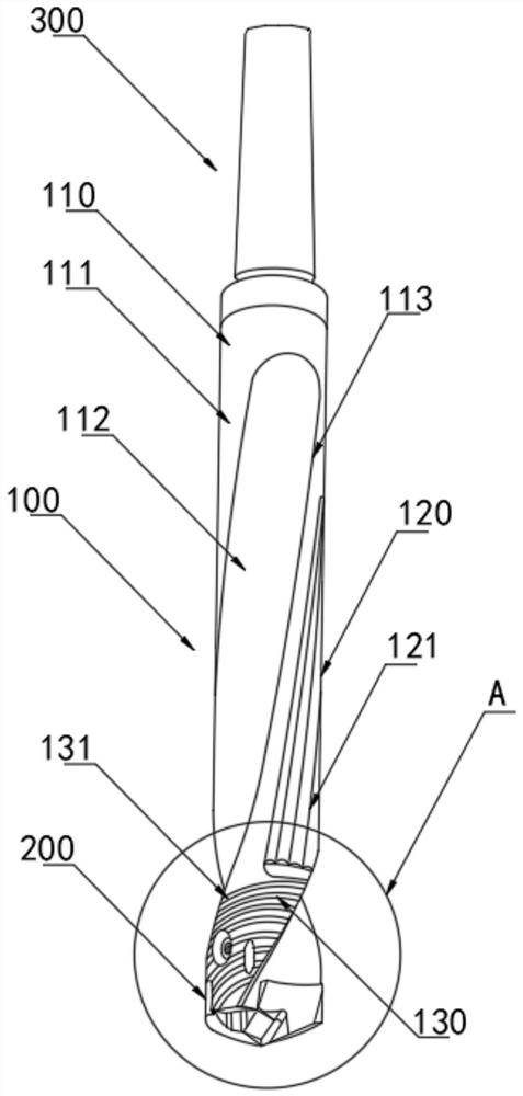
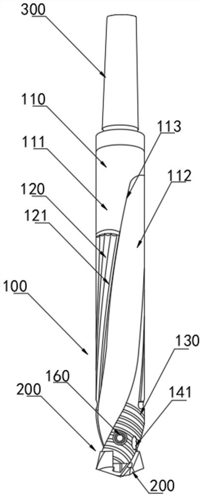
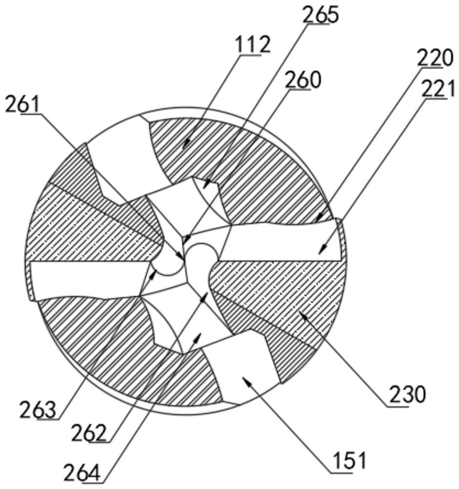
[0034] Embodiment 1, with reference to attached Figure 1-11 , a composite material hole processing PCD drilling and milling chamfering tool provided by the present invention includes a drill rod 100, a cutting head 200 and a tail handle 300. The outer wall of the drill rod 100 is spirally provided with a chip removal groove 112, and the chip removal groove 112 is provided with two There is a knife back 110 between the two groups of chip removal grooves 112, a limit groove 150 is provided on both sides of the bottom of the drill pipe 100, and the chip removal groove 112 extends downward to connect with the limit groove 150, and the bottom of the tool back 110 is fixedly installed with a convex Block 151, drill pipe 100 bottom is provided with through hole 170, and drill pipe 100 bottom is provided with cutting head 200, and cutting head 200 top is fixedly installed limit column 210, and limit column 210 two sides are provided with groove two 211, and cutting head 200 Limiting ...

Embodiment 2

[0045] Refer to the attached Figure 12 , a composite material hole processing PCD drilling and milling chamfering tool of this embodiment also includes an extended drill rod 180;

[0046] Further, the drill rod 100 also includes an extended drill rod 180, the outer wall of the extended drill rod 180 is spirally provided with chip guide grooves 181, and two sets of chip guide grooves 181 are provided. Specifically, according to the different hole depths, the extended drill rod 180 and the drill bit Choose according to the multiple diameter. When drilling on the CNC, the drill pipe 100 with a small multiple diameter ratio is more rigid. When the cutting head 200 drills to the bottom, the chips can be removed smoothly. If the length is not enough, the surface finish will deteriorate. , The problem of unequal hole diameter and drill bit breakage, chips will block the sub-flutes, and the extended drill rod 180 needs to be used to solve the problem.

[0047] The specific implement...


PUM


Abstract

The invention belongs to the technical field of milling cutters, and is specifically a composite material hole processing PCD drilling and milling chamfering tool, including a drill rod, a cutting head and a tail handle. The technical solution is: the outer wall of the drill rod is spirally provided with chip removal There are two groups of chip removal grooves, a knife back is arranged between the two groups of chip removal grooves, and a limiting groove is provided on both sides of the bottom of the drill rod, and the chip removal grooves extend downward to meet the limiting grooves. One connection, the bottom of the knife back is fixedly installed with a bump, the bottom of the drill rod is provided with a through hole, the bottom of the drill rod is provided with a cutting head, and the top of the cutting head is fixedly installed with a limiting column. The beneficial effects of the present invention are: The polycrystalline diamond blade is welded through the inner wall of the installation groove, the limit column is inserted into the through hole at the bottom of the drill pipe, the cutting head is connected with the limit groove one, and the protrusion of the drill pipe is inserted into the limit groove two of the cutting head, so that the groove two Perpendicular to the axis of the threaded hole, the screw is fixed to the groove 2 of the limit post, which has the effect that the new blade and cutter head can be replaced, and the cutter bar can be used repeatedly.

Description

technical field [0001] The invention relates to the technical field of milling cutters, in particular to a PCD drilling and milling chamfering tool for machining holes made of composite materials. Background technique [0002] PCD has been used in cutting as a superhard tool material for hundreds of years. In the 1970s, people used high-pressure synthesis technology to synthesize polycrystalline diamond PCD, which solved the problem of scarcity and high price of natural diamond. The range of application of knives extends to aviation, aerospace, automobiles, electronics, stone and other fields. [0003] The prior art has the following disadvantages: when the cutting edge of the existing knives is worn or blunt and not sharp, it can be sharpened on a special sharpening machine, and can be used after sharpening, but after several times of sharpening, the entire The tool bar will be scrapped, and the thermal stability of PCD tools is poor. When the cutting temperature exceeds 7...

Claims


Application Information

Patent Timeline
Patent Type & Authority Patents(China)
IPC IPC(8): B23B51/08B23B51/06B23C5/00B23C5/28
CPCB23B51/06B23B51/08B23C5/00B23C5/28
Inventor 凌喜乐林鹏杨勇陈继亮凌一诺
Owner 河源市蓝海米克模具刀具有限公司
Learn More