Tubular workpiece coating machine

A coating machine and workpiece technology, applied in the field of tubular workpiece coating machines, can solve problems such as deformation and reduce coating efficiency of tubular workpieces, and achieve the effects of improving coating efficiency, ensuring coating uniformity, and reducing coating time.

Pending Publication Date: 2021-03-09
XIANGTAN HONGDA VACUUM TECH CO LTD
View PDF6 Cites 3 Cited by
  • Summary
  • Abstract
  • Description
  • Claims
  • Application Information

AI Technical Summary

Problems solved by technology

[0003] However, when coating a tubular workpiece, it is difficult to rotate it to make the coating more uniform when it is placed horizontally and coated in a vacuum environment, and due to the tubular The workpiece is long and will be deformed. As a result, when coating a tubular workpiece, it may be necessary to take out and replace it with another half of the circumference after coating half of the circumference, which greatly reduces the coating efficiency of the tubular workpiece.

Method used


Image

  • Tubular workpiece coating machine
  • Tubular workpiece coating machine

Examples


Embodiment Construction

[0019] Next, the technical solutions in the embodiments of the present invention will be described in contemplation in the embodiments of the present invention, and clearly, as described herein is merely, not all of the embodiments of the present invention. Based on the embodiments of the present invention, those of ordinary skill in the art will belong to the scope of the present invention without all other embodiments obtained without creative labor.

[0020] It should be noted that all directional indications (such as above, lower, left, right, front, and then ...) are intended to be interpreted between the components under a particular attitude (as shown in the drawings). The relative positional relationship, the movement condition, etc., if the specific posture changes, the directional indication is also correspondingly changed.

[0021] In addition, as described in the present invention, as described in the present invention, it is only for the purpose of describing purposes...


PUM


Abstract

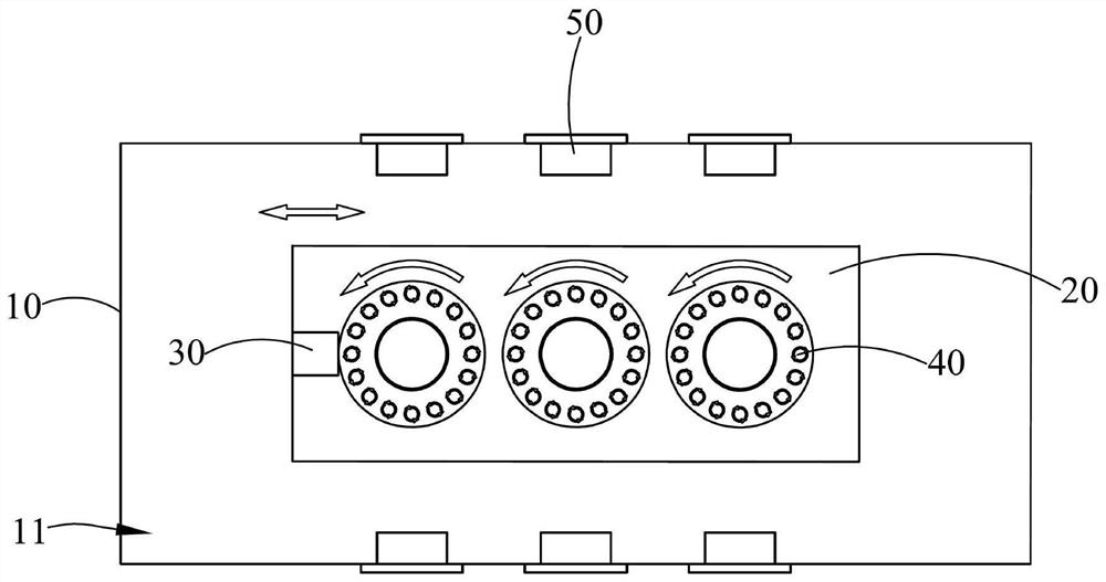
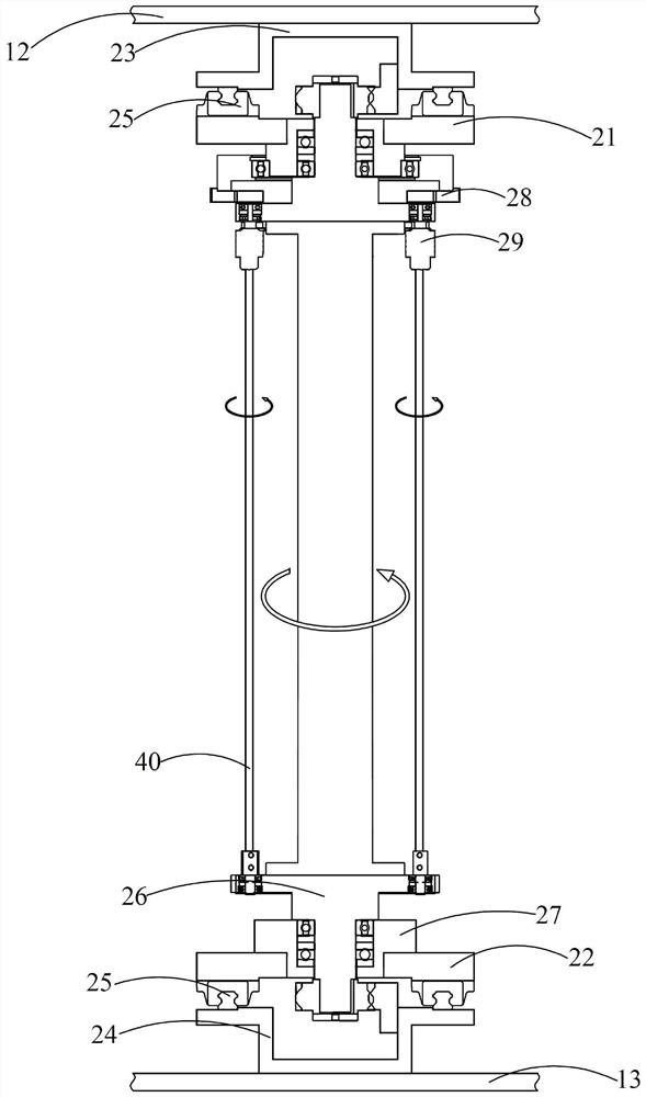
The invention discloses a tubular workpiece coating machine. The tubular workpiece coating machine comprises a coating bin internally provided with a coating cavity, a workpiece frame arranged in thecoating cavity in a sliding manner and a first driving motor connected with the workpiece frame to drive the workpiece frame to slide in the length direction of the coating bin. At least one tubular workpiece is borne on the workpiece frame, a plurality of cathodes are arranged in the length direction of the coating bin at intervals, the tubular workpiece coating machine further comprises a seconddriving motor arranged in the coating cavity, and the second driving motor is connected with the workpiece frame so as to drive the workpiece frame to rotate around the axis of the workpiece frame. The invention provides the coating machine suitable for the tubular workpiece.

Description

Technical field [0001] The present invention relates to the field of vacuum plating, and more particularly to a tubular workpiece coating machine. Background technique [0002] The vacuum coating is currently a relatively foremost coating technique, and the magnetron sputter coating method in the vacuum coating is used to discharge electrons by a power-electrode, and the gas molecule in the vacuum chamber is collided with gas molecules within the vacuum chamber under the acceleration of the electric field, thereby causing gas molecules. Ionization, the ionized gas molecules bombard the metal particles on the cathode under the action of the electric field, and the metal particles are ionizing the sputtering, and the electroplated metal ions are deposited to form a film surface, wherein the electrons can be more efficient. Collipite with gas molecules, thereby increasing the gas molecular ionization ratio, using the magnet to form a magnetode in the cathode, so the electron is form...

Claims


Application Information

Patent Timeline
Patent Type & Authority Applications(China)
IPC IPC(8): C23C14/50C23C14/35
CPCC23C14/505C23C14/352
Inventor 唐洪波左莉黄乐祝海生孙桂红黄国兴
Owner XIANGTAN HONGDA VACUUM TECH CO LTD
Why Eureka
Try Eureka