Steel plate cutting equipment

A technology for cutting equipment and steel plates, applied in metal processing equipment, other manufacturing equipment/tools, clamping, etc., can solve the problems of chamfering and grinding at the edges that cannot be cut by steel plates, so as to reduce processing procedures and prevent improper cutting Qualified, guarantee the effect of cutting accuracy

Active Publication Date: 2021-03-12
聊城市海力机箱有限公司
View PDF12 Cites 2 Cited by
  • Summary
  • Abstract
  • Description
  • Claims
  • Application Information

AI Technical Summary

Problems solved by technology

The disadvantage of this invention is that it is impossible to chamfer and grind the edges of steel plate cutting

Method used


Image

  • Steel plate cutting equipment
  • Steel plate cutting equipment
  • Steel plate cutting equipment

Examples


specific Embodiment approach 1

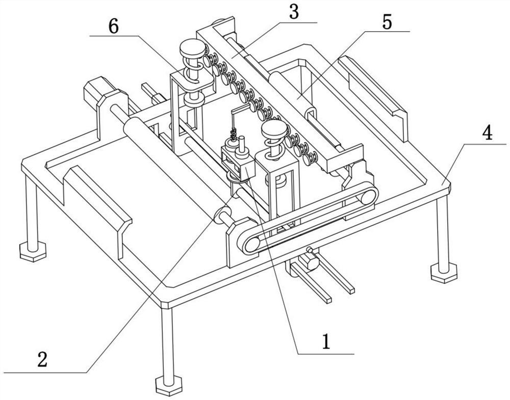
[0029] Combine below Figure 1-7 In this embodiment, a steel plate cutting equipment includes a processing assembly 1, an adjustment assembly 2, a cleaning assembly 3, a support assembly 4, a transport assembly 5 and a pressing assembly 6, the processing assembly 1 is fixedly connected to the adjustment assembly 2, The adjustment assembly 2 is fixedly connected to the support assembly 4 , the cleaning assembly 3 is fixedly connected to the support assembly 4 and the transportation assembly 5 , the support assembly 4 is connected to the transportation assembly 5 , and the pressing assembly 6 is fixedly connected to the support assembly 4 .

[0030] The cutting of the steel plate and the chamfering and grinding of the cut edge of the steel plate can be realized through the processing component 1, which reduces the processing steps of the steel plate and prevents burrs and sharp metal corners from scratching the operator; it can also be opened and cleaned through the processing co...

specific Embodiment approach 2

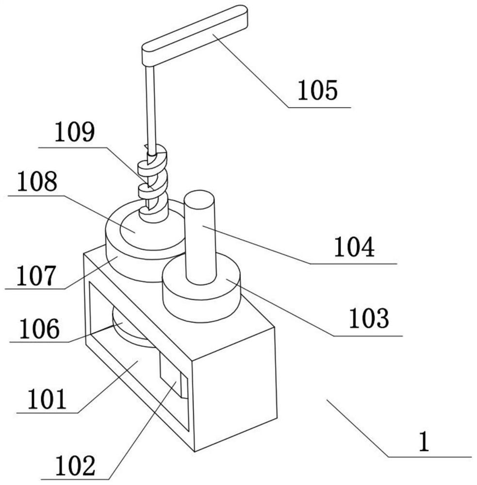
[0032] Combine below Figure 1-7 To illustrate this embodiment, the processing assembly 1 includes a processing frame 101, a cutting motor 102, a cutting gear 103, a cutting knife 104, an L-shaped rod 105, a grinding shaft 106, a grinding gear 107, a chamfering wheel 108 and a grinding chip removal wheel 109 , the cutting motor 102 is fixedly connected on the processing frame 101, the cutting gear 103 is fixedly connected on the output shaft of the cutting motor 102, the cutting knife 104 is fixedly connected on the cutting gear 103, and the L-shaped rod 105 is screwed on the processing frame 101, The grinding shaft 106 is rotatably connected to the processing frame 101, the grinding gear 107 is fixedly connected to the grinding shaft 106, the chamfering wheel 108 is fixedly connected to the grinding gear 107, and the grinding chip removal wheel 109 is fixedly connected to the chamfering wheel 108.

specific Embodiment approach 3

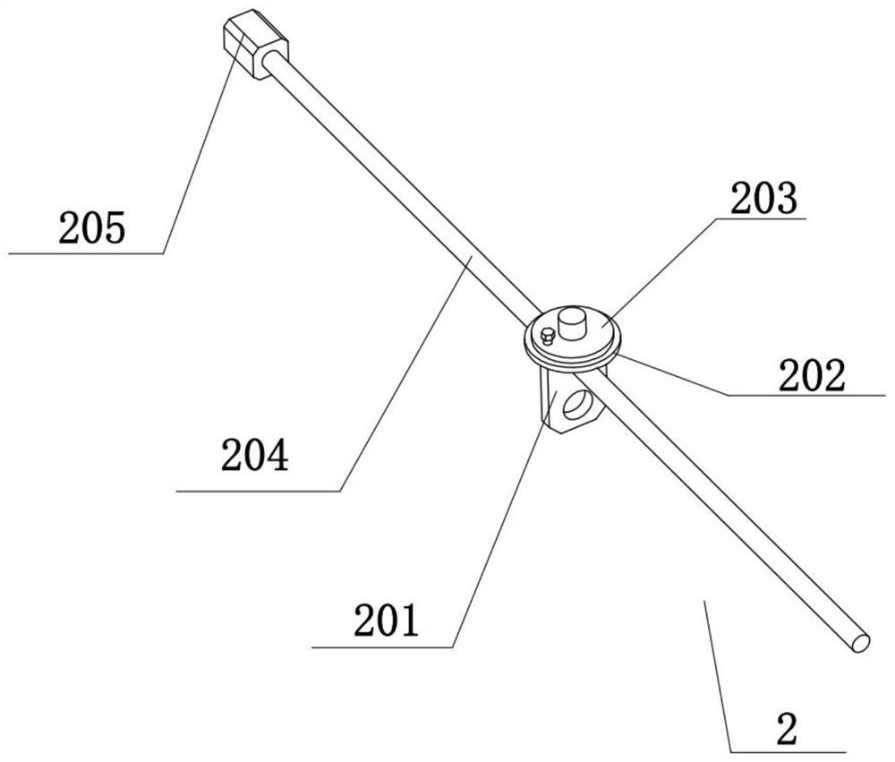
[0034] Combine below Figure 1-7To illustrate this embodiment, the adjustment assembly 2 includes a feed plate 201, a fixed table 202, a rotary table 203, a feed screw 204 and a feed motor 205, the feed plate 201 is fixedly connected with a fixed table 202, and the fixed table 202 is Rotationally connected with a turntable 203, the turntable 203 is fixedly connected with a processing frame 101, the feed screw 204 is rotatably connected to the support assembly 4, the feed motor 205 is fixedly connected to the support assembly 4, and the feed screw 204 is fixedly connected to the feeder assembly 4. On the output shaft of the motor 205, the feed plate 201 and the feed screw 204 are driven by threads.


PUM


Abstract

The invention relates to the technical field of cutting equipment, in particular to steel plate cutting equipment which has the advantage of being capable of chamfering and polishing cut edges of steel plates. The steel plate cutting equipment comprises a machining assembly, an adjusting assembly, a cleaning assembly, a supporting assembly, a conveying assembly and a pressing assembly, wherein themachining assembly is fixedly connected to the adjusting assembly, the adjusting assembly is fixedly connected to the supporting assembly, the cleaning assembly is fixedly connected to the supportingassembly and the conveying assembly, the supporting assembly is connected to the conveying assembly, and the pressing assembly is fixedly connected to the supporting assembly.

Description

technical field [0001] The invention relates to the technical field of cutting equipment, in particular to a steel plate cutting equipment. Background technique [0002] The invention with the publication number CN108015384A discloses a steel plate cutting equipment, including a steel plate cutting equipment body, an operation panel, a support frame, a bottom plate, a first spring, a first rail, a support seat, a first slider, a second rail, and a cutting knife Device, second slider, control panel, measuring device, sensing device, alarm device, host, lock, first clamping block, first electric push rod, second clamping block, solenoid valve, second electric push rod , pulley groove, wheel shaft, micro switch, contact, upper clamping disc, second spring, cutter head, lower clamping disc, torch clamp, automatic height adjuster, signal line, DC motor, cable, Hall sensor and lead screw, the lower end of the steel plate cutting equipment body is connected with a support frame; t...

Claims


Application Information

Patent Timeline
Patent Type & Authority Applications(China)
IPC IPC(8): B23P23/00B23Q7/00B23Q3/00B23Q5/34B23Q5/40B23Q11/10B23Q11/00
CPCB23P23/00B23Q3/00B23Q5/34B23Q5/40B23Q7/00B23Q11/0042B23Q11/10
Inventor 佟万国魏永涛
Owner 聊城市海力机箱有限公司
Why Eureka
Try Eureka