Clock delay detection method and device, clock delay compensation method and device, terminal and readable storage medium

A clock delay and detection method technology, applied in the field of communication, can solve problems such as large errors, inconsistent impedance matching, and inability to use

Pending Publication Date: 2021-03-12
ZTE CORP
View PDF0 Cites 6 Cited by
  • Summary
  • Abstract
  • Description
  • Claims
  • Application Information

AI Technical Summary

Problems solved by technology

Due to the different lengths of traces from the main clock to the backplane and connectors between different slots, there are different delay errors when the synchronous clock arrives at each service card. The error ranges from a few nanoseconds to hundreds of nanoseconds, resulting in different There is a delay error between the phases of the service cards between the slots and the reference phase of the main clock. This error makes the switch unusable in high-precision clock synchronization scenarios.
[0003] Existing communication equipment mainly adopts the traditional method of manually compensating the delayed phase of the synchronous clock, which uses an instrument with time and phase detection functions to measure the synchronous clock signal of the main clock module across the backplane to the service card from the clock until it is synchronized The delay time on the chip is then compensated at the start of the business in the form of a

Method used


Image

  • Clock delay detection method and device, clock delay compensation method and device, terminal and readable storage medium
  • Clock delay detection method and device, clock delay compensation method and device, terminal and readable storage medium
  • Clock delay detection method and device, clock delay compensation method and device, terminal and readable storage medium

Examples


Embodiment 1

[0052] See figure 1 , a clock delay detection method provided in this embodiment includes:

[0053] S101: Transmit the first synchronous clock to the clock module to be detected through the first physical link;

[0054] S102: Receive the feedback clock transmitted by the clock module to be detected through the second physical link;

[0055] S103: Determine the delay of the clock module to be detected.

[0056] In some embodiments, the clock delay detection method in the embodiment of the present invention is applied to a switch device, and the switch device includes but is not limited to: a main clock module, a transmission link, a clock module to be detected, and a storage module;

[0057] Among them, the main clock module is the core clock module in the switch equipment, and its function can accept the synchronization of clock devices and equipment such as time server, GPS antenna, BITS clock, 1588 module, etc., and can also be synchronized with internal devices and equipm...

Embodiment 2

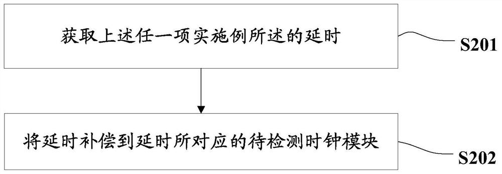
[0090] See figure 2 , a clock delay compensation method provided in this embodiment includes:

[0091] S201. Obtain the time delay described in any one of the above embodiments;

[0092] S202. Compensate the delay to the clock module to be detected corresponding to the delay.

[0093] It should be noted that the delay compensation to the clock module to be detected corresponding to the delay can be performed manually or automatically.

[0094] In some embodiments, the delay is compensated to the clock module to be detected corresponding to the delay, and the compensation methods include but are not limited to the following methods:

[0095] Compensate the delay to the constant delay memory of the clock module to be detected through the management interface, and the clock module to be detected will remove the delay during subsequent clock synchronization calculations;

[0096] or,

[0097] Modifying the phase of the second synchronous clock, so that the second synchronous ...

no. 3 example

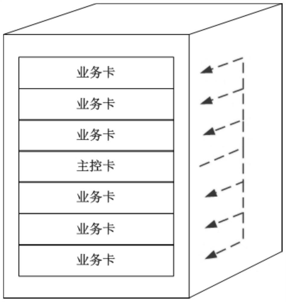
[0108] The method for detecting and compensating clock delays provided by the above embodiments will be specifically described below by taking an application scenario in which the method provided by the above embodiments is applied to a rack switch as an example.

[0109] It should be noted that the methods provided by the present invention are not limited to being applied to rack switches, and the following is only an exemplary description. Other switch devices that use physical links to transmit synchronous clocks are also applicable to the method provided by the present invention.

[0110] see image 3 , image 3 It is a schematic diagram of the topology of a rack-mounted switch. The switch is composed of a main control card and multiple service cards.

[0111] see Figure 4 , Figure 4 It is a topological schematic diagram of clock delay detection and compensation, and the device includes a main clock module, a clock module to be detected, a storage module, a first ph...


PUM


Abstract

The embodiment of the invention provides clock delay detection and compensation methods and devices, a terminal and a readable storage medium, and the clock delay detection method comprises the steps:transmitting a first synchronous clock to a to-be-detected clock module through a first physical link; receiving a feedback clock which is transmitted by the to-be-detected clock module through a second physical link and is adjusted according to the phase of the first synchronous clock, and determining the delay of the to-be-detected clock module according to the feedback clock, the self-return clock, the delay parameter corresponding to the first physical link and the delay parameter corresponding to the second physical link. The invention also provides the clock delay detection and compensation methods and devices, the terminal and the readable storage medium. By calculating the delay of a main clock module and the delay caused by the physical characteristics of a first physical link and a second physical link, the error of time delay caused by detecting clock distribution of switch equipment can be further reduced, so that the precision of clock time delay detection is improved.

Description

technical field [0001] Embodiments of the present invention relate to but are not limited to the field of communication technologies, and specifically, relate to but are not limited to a clock delay detection and compensation method, device, terminal, and readable storage medium. Background technique [0002] With the continuous improvement of network throughput, there are more and more types of service cards and rack slots for large-capacity switches. The system architecture of the clock of the whole switch is usually composed of a synchronous clock network distributed by the master clock. The slave clocks of each service card receive the synchronous clock delivered by the master clock through the backplane, and synchronize its frequency and phase. Due to the different lengths of traces from the main clock to the backplane and connectors between different slots, there are different delay errors when the synchronous clock arrives at each service card. The error ranges from a...

Claims


Application Information

Patent Timeline
IPC IPC(8): G06F1/12G06F1/10H04J3/06
CPCG06F1/12G06F1/10H04J3/0682H04J3/0685
Inventor 续博雄
Owner ZTE CORP
Why Eureka
Try Eureka