Cathode arc head with double-layer shielding cover

A technology of shielding cover and cathode arc, which is applied in the direction of coating, metal material coating process, ion implantation plating, etc., can solve the problems of long-term stable ablation of arc source, limited movement of arc spot, and cathode The target utilization rate is not high, so as to reduce the frequency of replacement, reduce the impact, and facilitate maintenance

Inactive Publication Date: 2021-03-16
廖斌 +1
View PDF1 Cites 0 Cited by
  • Summary
  • Abstract
  • Description
  • Claims
  • Application Information

AI Technical Summary

Problems solved by technology

[0005] The cathode arc head in the prior art adopts a single-layer shielding cover, which has limited restraint on the movement of the arc spot, and cannot well ensure the long-term stable ablation of the arc source, and it is easy to form deep pits on the surface of the cathode target to cause arc interruption. The utilization rate of the cathode target is not high, and the replacement of the cathode target affects the efficiency of use

Method used


Image

  • Cathode arc head with double-layer shielding cover
  • Cathode arc head with double-layer shielding cover
  • Cathode arc head with double-layer shielding cover

Examples


Embodiment 1

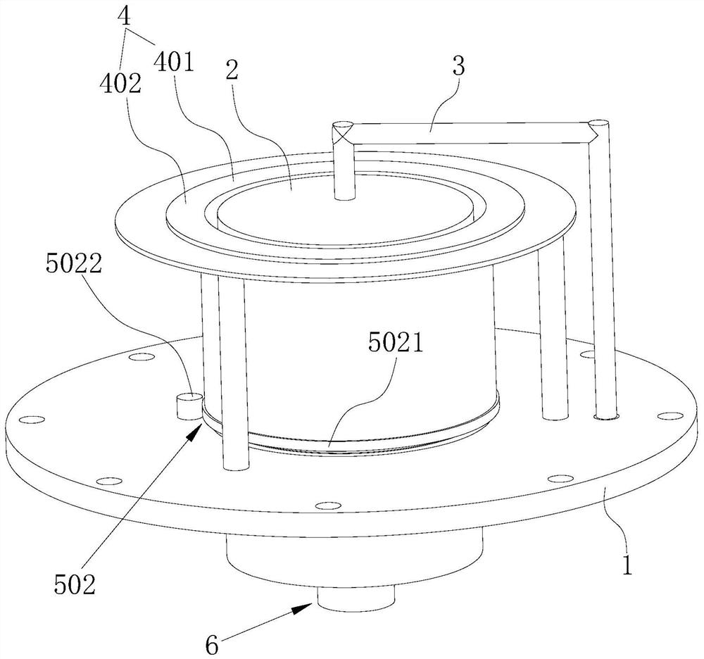
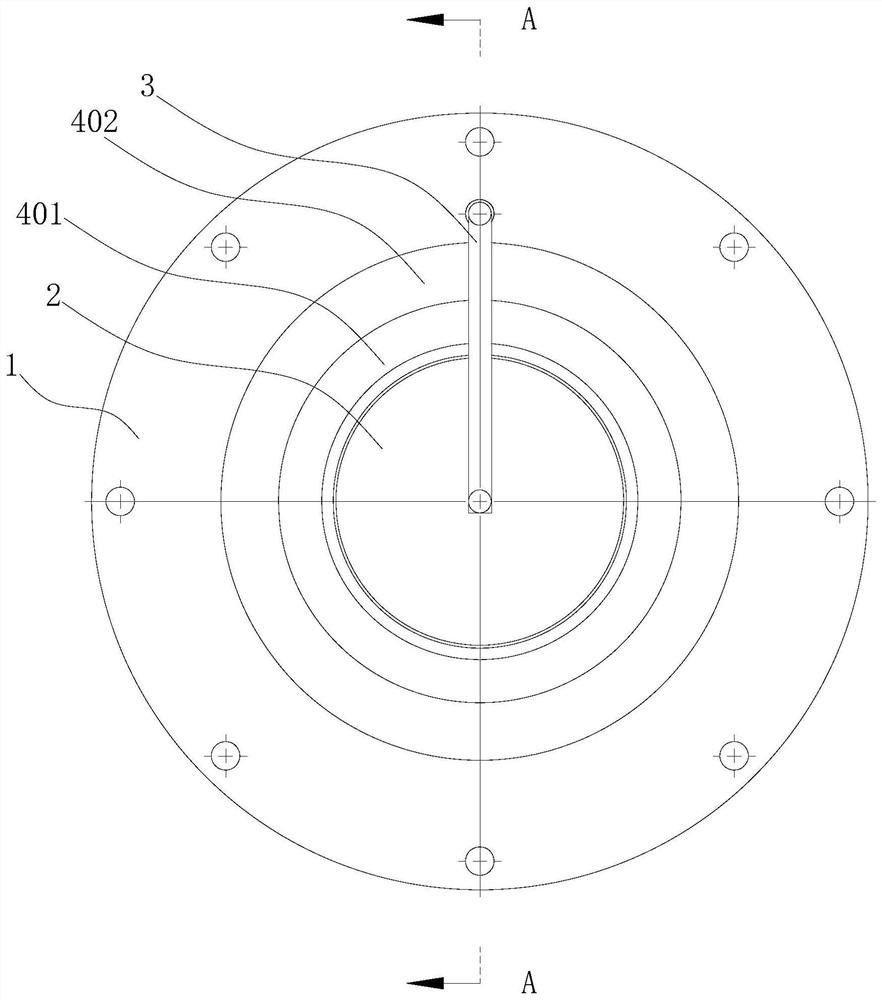
[0037] refer to figure 1 , figure 2 as well as image 3 , this embodiment discloses a cathode arc head with a double-layer shield, including a fixed flange 1, a cathode target 2, a trigger electrode 3, a shielding system 4, an auxiliary anode plate (not shown in the figure), and a cathode The target material 2 is fixed on the fixed flange 1, and the trigger electrode 3 is rotatably arranged on the fixed flange 1. This is an existing structure, and will not be repeated here.

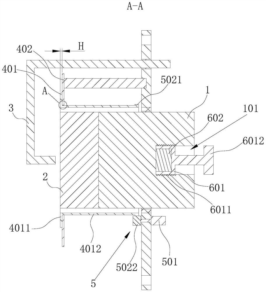
[0038] refer to figure 1 , figure 2 , image 3 as well as Figure 4 , the shielding system 4 includes a first shielding case 401 and a second shielding case 402, the first shielding case 401 and the second shielding case 402 are coaxially arranged with the cathode target 2, and the first shielding case 401 and the second shielding case 402 Both are placed outside the cathode target 2 and keep a distance of 1 mm to 10 mm between the cathode target 2 in the radial direction. The first shield 401 and...

Embodiment 2

[0049] This embodiment discloses another cathode arc head with a double-layer shield. Based on Embodiment 1, the differences between this embodiment and Embodiment 1 are:

[0050] The rotating drive assembly includes a drive motor and a transmission assembly. The drive motor is fixed on the fixed flange. The transmission assembly includes a transmission chain ring, a transmission sprocket wheel, and a chain belt. The transmission chain ring is arranged on the outer wall of the first shielding case. The transmission chain ring includes Meshing teeth, the meshing teeth of the chain belt and the transmission chain ring and the transmission sprocket;

[0051] The transmission sprocket and the drive motor shaft are fixed, and the drive sprocket and drive motor shaft can pass through spline couplings, involute spline couplings, axially movable radial key rigid couplings, drum-shaped One of the methods of gear coupling or feather key connection.


PUM


Abstract

The invention discloses a cathode arc head with a double-layer shielding cover, and relates to the field of ion beam generation devices. According to the scheme, a fixed flange plate, a cathode targetmaterial, a trigger electrode, a shielding system and an auxiliary anode plate are included, the shielding system comprises a first shielding cover and a second shielding cover, the first shielding cover and the second shielding cover are both coaxial with the cathode target material, both sleeve the cathode target material and are kept to be spaced from the cathode target material, the first shielding cover is made of a magnetic conductive material, and the second shielding cover is made of a non-magnetic conductive material. The double-layer shielding cover is arranged, so that arc spots onthe cathode target material are better restrained, the surface of the cathode target material is uniformly ablated, the utilization rate of the cathode target material is improved, the replacement frequency of the cathode target material is reduced, and the influence on production is reduced.

Description

technical field [0001] The invention relates to the field of ion beam generating devices, in particular to a cathode arc head with a double-layer shielding cover. Background technique [0002] Metal ion implantation can comprehensively improve the friction, wear, corrosion and high temperature oxidation resistance of the material surface, and its surface modification effect is more significant than that of nitrogen ion implantation, and its application range is also wider. [0003] The metal cathode vacuum arc plasma source has the characteristics of high metal plasma ionization rate, large output of metal ions, high ion purity, can generate plasma of almost all metals, and simple structure. However, the large particles produced by the cathodic arc are unfavorable for the application of this source. With the increasing application of cathodic arc plasma industry, especially the emergence of a new generation of surface technologies such as nano-laminated films and superhard ...

Claims


Application Information

Patent Timeline
Patent Type & Authority Applications(China)
IPC IPC(8): C23C14/48
CPCC23C14/48
Inventor 廖斌庞盼王国梁罗军陈琳
Owner 廖斌
Why Eureka
Try Eureka