All-optical microwave frequency shift phase shift device based on Sagnac loop and I/Q detection and measurement method

A technology of frequency shifting and microwave, applied in measuring devices, frequency measuring devices, measuring electrical variables, etc., can solve complex stability problems and achieve the effects of improving stability and accuracy, strong operability, and simple structure

Active Publication Date: 2021-03-16
NORTHWESTERN POLYTECHNICAL UNIV
View PDF4 Cites 0 Cited by
  • Summary
  • Abstract
  • Description
  • Claims
  • Application Information

AI Technical Summary

Problems solved by technology

However, currently publicly reported microwave photon measurement systems usually use multiple modulators cascaded to achieve signal measurement, which is relatively complex and has poor stability.

Method used


Image

  • All-optical microwave frequency shift phase shift device based on Sagnac loop and I/Q detection and measurement method
  • All-optical microwave frequency shift phase shift device based on Sagnac loop and I/Q detection and measurement method
  • All-optical microwave frequency shift phase shift device based on Sagnac loop and I/Q detection and measurement method

Examples


Embodiment 1

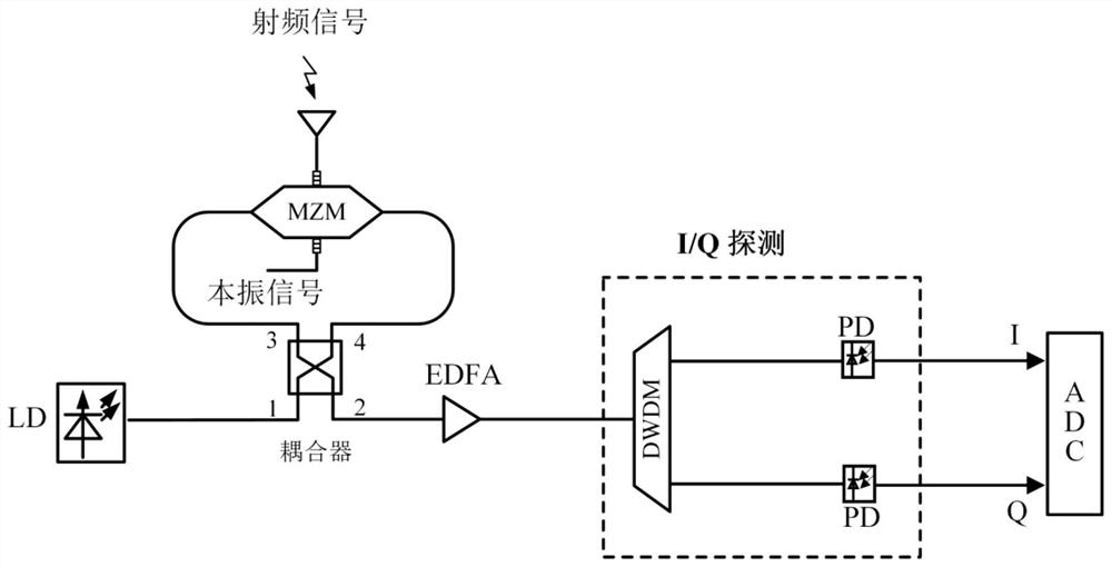
[0044] EXAMPLES A device includes: a laser source, optical coupler, DE-MZM, DC voltage source, two microwave signal sources, EDFA, DWDM, PD, spectrum, and oscilloscope. Two microwave signal sources generate this vibrating signal and two radio frequency signals to be tested, and the two signals are connected to the two RF ports of the DE-MZM, and the DC bias of the modulator is controlled by the DC voltage source. DWDM Separate the upper and lower sides of the modulated optical signal, divided into two light signals, the two outputs of the DWDM are connected to the input of the PD, and the PD output is connected to the oscilloscope, and the time domain waveform is sampled by the oscilloscope, and passed the computer The size and direction of Doppler shift can be obtained by calculation.

[0045] The optical carrier wavelength generated by the laser source is 1549.9 nm, and the optical power is 12 dBm; the two microwave signal sources generate a frequency of 20 GHz, the power 10dBm ...

Embodiment 2

[0048] Next, phase measurement is performed in an embodiment.

[0049] The radio frequency signal source generates a frequency 20 GHz, a power 10dBm radio frequency signal; the radio frequency signal source generates a frequency of 20 GHz, the power is 0 dBm, and the phase to be measured by the phase-to-measure signal to be measured, The response of the PD is 0.8A / W;

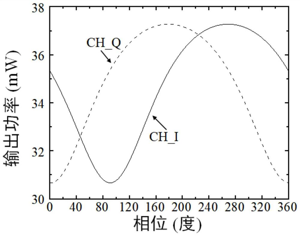
[0050] The I and QIg devices and settings are constant. The two PD output signals are input to the oscilloscope. The phase of the signal to be measured is changed by the phase shifter. The power of the two output signals comes from the phase shift. image 3 ;

[0051] The two signal output signal power is input to the computer, and the phase is calculated by MATLAB, and the measurement is met. Figure 4 .

[0052] In summary, the present invention is based on the full-optical microwave measuring apparatus and method of SAGNAc ring and I / Q detection, and it is easy to implement, and the work band is large, and the...


PUM


Abstract

The invention provides an all-optical microwave frequency shift phase shift device based on a Sagnac loop and I/Q detection. An optical signal output from a laser source is injected into a DE-MZM through an optical coupler, and a bias point of the DE-MZM is controlled through a DC bias voltage; and an optical signal output by the optical coupler is amplified through EDFA, then an upper sideband and a lower sideband are separated through DWDM, the upper sideband and the lower sideband form an optical signal, the two optical signals enter the input end of one PD, a photocurrent is obtained afterphotoelectric detection, and Doppler frequency shift information or phase information carried by the photocurrent is processed through a rear-end ADC. According to the invention, frequency and phasemeasurement of signals is realized, the structure is simple, and the operability is high; and a modulator with a high degree of symmetry and accurate bias control are adopted to improve the stabilityand accuracy of a measurement system, and a high-precision and stable broadband microwave photon measurement system is realized.

Description

Technical field [0001] The present invention relates to the field of microwave photon measurement, in particular microwave photon Doppler frequency shift measurement and phase measurement. Background technique [0002] The microwave measurement system is an indispensable module in modern electronic devices. In satellite communication, electronic confrontation, and radar systems, high-speed broadband microwave signals with high operating frequency up to dozens of GHz are required, which makes a huge challenge for the speed and bandwidth of the microwave measurement system. [0003] In recent years, microwave photon measurement technology has aroused great interest in people in an emerging research area. It can utilize the inherent advantages of photonics, such as large instantaneous bandwidth, anti-electromagnetic interference, etc., perform a wide-wide microwave signal Doppler frequency shift and phase measurement over a wide frequency range. At the same time, the electromagnetic...

Claims


Application Information

Patent Timeline
Patent Type & Authority Applications(China)
IPC IPC(8): G01R23/02G01R25/00
CPCG01R23/02G01R25/00Y02D30/70
Inventor 高永胜康博超徐源皓谭庆贵贺丰收樊养余刘准钆
Owner NORTHWESTERN POLYTECHNICAL UNIV
Why Eureka
Try Eureka