
Surgical injection equipment for child treatment

An injection equipment and surgical technology, applied in the field of surgical injection equipment for children's treatment, can solve problems such as difficulty in cooperating with medical staff, syringe body shaking, muscle tissue damage, etc., to avoid contact between medicinal liquid and air, controllable injection depth, The effect of increasing intelligence

Inactive Publication Date: 2021-03-19
沈丽萍
View PDF0 Cites 0 Cited by
  • Summary
  • Abstract
  • Description
  • Claims
  • Application Information

AI Technical Summary

Problems solved by technology

[0003] However, there are still some shortcomings in its actual use. For example, some vaccines have requirements for the injection depth. For example, if the BCG injection is too deep, it is easy to cause abscess at the injection site. In severe cases, repeated infection, abscess formation, and then rupture to form a hole
Generally speaking, BCG vaccination also has a certain risk of tuberculosis infection, but the risk will be relatively low. Too deep injection mainly causes local abscesses
Moreover, most children are afraid of intramuscular injections. When they see the syringe, they are prone to emotional tension and body shaking, and it is difficult to cooperate with the work of medical staff. If the child's body moves arbitrarily during the injection, it is easy to cause muscle tissue damage.

Method used


Image

  • Surgical injection equipment for child treatment
  • Surgical injection equipment for child treatment
  • Surgical injection equipment for child treatment

Examples


specific Embodiment approach

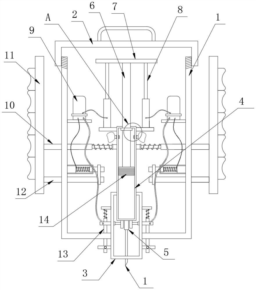
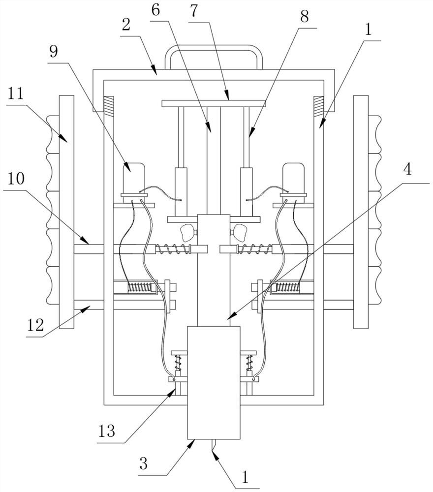
[0034] The specific implementation method is: by holding the grip bar 11, the power generation component 12 drives the cross bar 24 to move at this time, so that the cross bar 24 drives the linkage sleeve 23 to move laterally, so that the linkage sleeve 23 drives the magnet tube 21 to move laterally, that is, the magnet The magnetic induction line generated by the tube 21 is cut by the copper wire 22. At this time, the inside of the copper wire 22 generates a current, which is sent to the battery 9 through the wire, so that the drive of the device provides power, and then realizes the automatic process of the device. The practicability of the device is increased; it is fed into the battery 9 through wires, and at this time, the battery 9 guides the power into the hydraulic rod 8 and the limit assembly 13, and the hydraulic rod 8 pulls the top plate 7 to move down, so that the push rod 6 pushes the piston block 14 Move down, so that the liquid inside the syringe 4 is led out thr...


PUM


Abstract

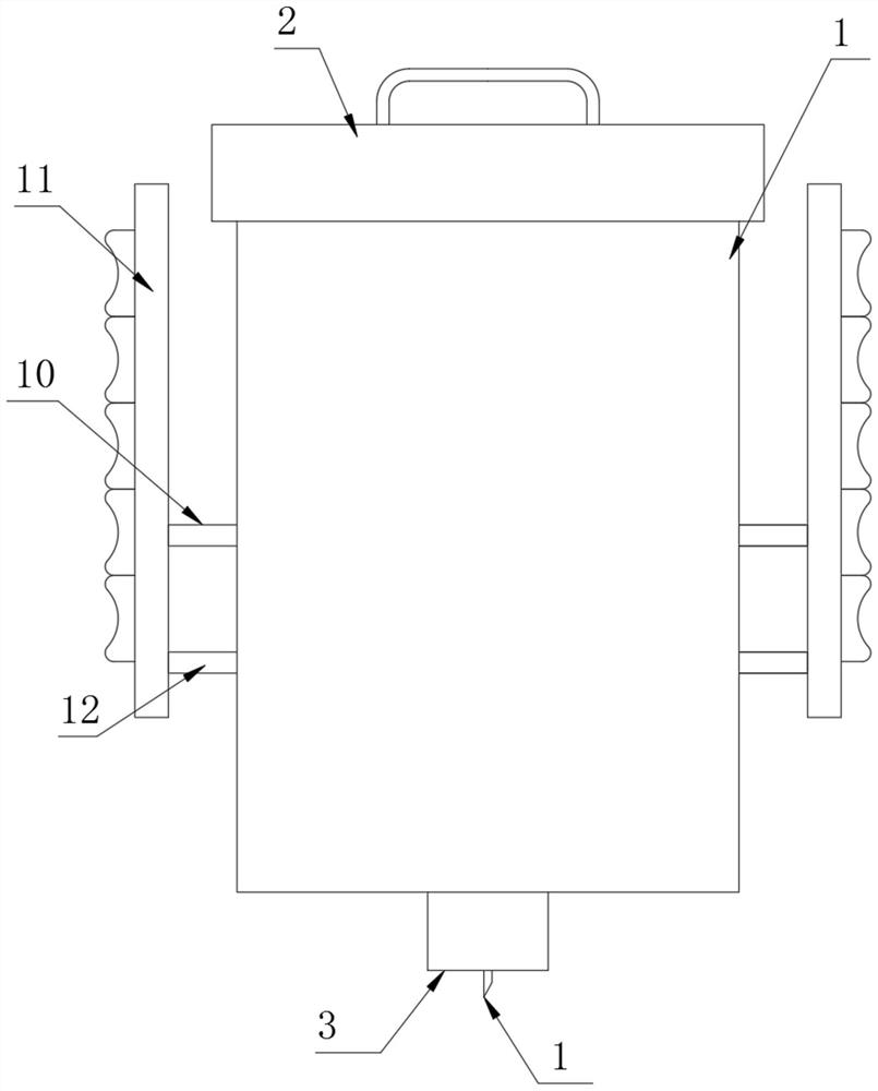
The invention discloses surgical injection equipment for child treatment, and particularly relates to the field of injection equipment. The surgical injection equipment comprises an outer cylinder, wherein a top cover is arranged at the top of the outer cylinder in a threaded sleeving mode, a bottom cylinder is fixedly mounted at the bottom of the outer cylinder, a needle cylinder is movably arranged at the top of the bottom cylinder in a sleeving manner, and a needle opening pipe is fixedly mounted at the bottom of the needle cylinder; and a push rod is movably arranged at the top of the needle cylinder in a sleeving manner, a piston block is fixedly mounted at the bottom extending into the needle cylinder, of the push rod, and the outer part of the piston block is attached to the inner wall of the needle cylinder. By holding holding rods, at the moment, a power generation assembly drives a corresponding transverse rod to move, and each transverse rod drives a corresponding linkage sleeve to move transversely, so that each linkage sleeve drives a corresponding magnet pipe to move transversely, namely, a magnetic induction line generated by each magnet pipe is cut by a corresponding copper wire, and at the moment, current is generated in each copper wire and fed into a corresponding storage battery through a wire. Therefore, the drive of the surgical injection equipment provides electric power, further the automation process of the surgical injection equipment is realized, and the practicability of the surgical injection equipment is improved.

Description

technical field [0001] The present invention relates to the technical field of injection equipment, and more specifically, the present invention relates to a surgical injection equipment for treating children. Background technique [0002] Intramuscular injection is a commonly used method of drug injection treatment. It refers to injecting medicinal liquid into muscle tissue through a syringe to achieve the purpose of curing diseases. , and when injecting drugs with strong irritants or large doses. When injecting, the needle generally enters about 2.5-3cm (2 / 3 of the needle, which is reduced for emaciated and sick children). Children's skin and muscle tissue are thin, and medical staff need to grasp the needle more accurately when injecting vaccines and drugs. depth. [0003] However, there are still some shortcomings in its actual use. For example, some vaccines have requirements for the injection depth. For example, if the BCG injection is too deep, it is easy to cause a...

Claims


Application Information

Patent Timeline
Patent Type & Authority Applications(China)
IPC IPC(8): A61M5/178A61M5/31A61M5/315
CPCA61M5/178A61M5/31A61M5/31511A61M5/31576A61M2005/31588
Inventor 沈丽萍
Owner 沈丽萍
Learn More