Three-stage three-section membrane separation system and method for capturing carbon dioxide in flue gas

A membrane separation system and carbon dioxide technology, which are applied in separation methods, use of liquid separation agents, chemical instruments and methods, etc., can solve the problems of unsatisfactory flue gas carbon capture membrane separation systems.

Pending Publication Date: 2021-03-19
TIANJIN UNIV
View PDF4 Cites 5 Cited by
  • Summary
  • Abstract
  • Description
  • Claims
  • Application Information

AI Technical Summary

Problems solved by technology

CO proposed by the U.S. Department of Energy (DOE) 2 The capture target is capture rate ≥ 90%, product gas CO 2 Volume content ≥ 95%, but none of the reported flue gas carbon capture membrane separation systems have reached this goal

Method used


Image

  • Three-stage three-section membrane separation system and method for capturing carbon dioxide in flue gas
  • Three-stage three-section membrane separation system and method for capturing carbon dioxide in flue gas
  • Three-stage three-section membrane separation system and method for capturing carbon dioxide in flue gas

Examples


Embodiment 1

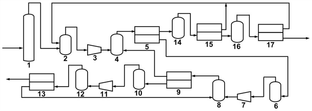
[0044] 1) CO in this embodiment 2 The raw flue gas with a content of 15% (volume content) is transported to the water washing tower (1), and NO is removed through pretreatment in the water washing tower (1) x and SO x and dust and other harmful gases and impurities, enter the first buffer tank (2) together with the permeate gas from the second-stage membrane separator (15) and the third-stage membrane separator (17), and enter the first-stage compression tank (2) after being mixed. Machine (3), compressed to 4.0bar, enters the first mixed humidification tank (4) together with the retained gas of the second-stage membrane separator (9), and enters the first-stage membrane separator (5) after being humidified and fully mixed ;

[0045] 2) The intercepted gas of the first-stage membrane separator (5) enters the fourth mixing humidification tank (14), and enters the second-stage membrane separator (15) after being humidified;

[0046] 3) The trapped gas of the second-stage memb...

Embodiment 2

[0053] 1) CO in this embodiment 2 The raw flue gas with a content of 15% (volume content) is transported to the water washing tower (1), and NO is removed through pretreatment in the water washing tower (1) x and SO x and dust and other harmful gases and impurities, enter the first buffer tank (2) together with the permeate gas from the second-stage membrane separator (15) and the third-stage membrane separator (17), and enter the first-stage compression tank (2) after being mixed. Machine (3), compressed to 4.5bar, enters the first mixed humidification tank (4) together with the retained gas of the second-stage membrane separator (9), and enters the first-stage membrane separator (5) after being humidified and fully mixed ;

[0054] 2) The intercepted gas of the first-stage membrane separator (5) enters the fourth mixing humidification tank (14), and enters the second-stage membrane separator (15) after being humidified;

[0055] 3) The trapped gas of the second-stage memb...

Embodiment 3

[0062] 1) CO in this embodiment 2 The raw flue gas with a content of 15% (volume content) is transported to the water washing tower (1), and NO is removed through pretreatment in the water washing tower (1) x and SO x and dust and other harmful gases and impurities, enter the first buffer tank (2) together with the permeate gas from the second-stage membrane separator (15) and the third-stage membrane separator (17), and enter the first-stage compression tank (2) after being mixed. Machine (3), compressed to 5.0bar, enters the first mixed humidification tank (4) together with the retained gas of the second-stage membrane separator (9), and enters the first-stage membrane separator (5) after being humidified and fully mixed ;

[0063] 2) The intercepted gas of the first-stage membrane separator (5) enters the fourth mixing humidification tank (14), and enters the second-stage membrane separator (15) after being humidified;

[0064] 3) The trapped gas of the second-stage memb...


PUM


Abstract

The invention relates to a three-stage three-section membrane separation system and method for capturing carbon dioxide in flue gas. Raw material flue gas is pretreated by a water washing tower to remove impurities, and enters a first-stage first-stage membrane separator after being compressed and humidified; the intercepted gas of the first-stage first-stage membrane separator is humidified and then enters a second-stage membrane separator, the intercepted gas of the second-stage membrane separator is continuously humidified and enters a third-stage membrane separator, and the intercepted gasof the third-stage membrane separator is directly emptied; the permeated gas of the second-stage membrane separator and the third-stage membrane separator are returned to an inlet of the first-stagefirst-stage membrane separator; the permeated gas of the first-stage first-stage membrane separator enters a second-stage membrane separator after being compressed and humidified, and the permeated gas of the second-stage membrane separator enters a third-stage membrane separator after being compressed and humidified; the trapped gas of the second-stage membrane separator returns to the inlet of the first-stage first-stage membrane separator, and the trapped gas of the third-stage membrane separator returns to the inlet of the second-stage membrane separator; the permeation gas of the third-stage membrane separator is carbon dioxide. The purity of carbon dioxide is greater than 95%, and the capture rate of carbon dioxide is greater than 70%.

Description

technical field [0001] The invention relates to a three-stage three-stage membrane separation system and method for flue gas carbon dioxide capture, which belongs to the field of membrane separation carbon dioxide capture and is suitable for power plants, cement plants, steel plants, and ammonia plants / coal gasification combined cycle power generation Flue gas carbon dioxide capture in various places such as factories; by adjusting the operating process parameters of the membrane separation system, specific carbon dioxide capture targets can be achieved. For the three-stage three-stage membrane separation system corresponding to the present invention, it is expected to take the lead in the world to realize or surpass the coal-fired power plant flue gas occasions with a typical low carbon dioxide concentration (volume content of 15%). The proposed capture target of carbon dioxide capture rate ≥ 90% and product gas carbon dioxide volume content ≥ 95%; for raw flue gas with a car...

Claims


Application Information

Patent Timeline
Patent Type & Authority Applications(China)
IPC IPC(8): B01D53/22B01D47/00B01D53/18
CPCB01D53/228B01D47/00B01D53/14B01D53/1456B01D53/1481B01D2258/0283B01D2257/504B01D2257/40Y02P70/10Y02C20/40
Inventor 王志伍泓宇李庆华赵颂王纪孝
Owner TIANJIN UNIV
Why Eureka
Try Eureka