Underground hydraulically-driven spiral-rotational flow coupling tubular separator

A technology of hydraulic drive and separator, which is used in the production of fluids, wellbore/well components, earth-moving drilling, etc. It can solve the problems of wellbore, equipment erosion, wear and blockage, goaf reservoir collapse, and wellbore instability, etc. problems, to avoid erosion, wear and blockage, reduce the volume of riser pipe, and reduce pump power.

Active Publication Date: 2021-03-19
SOUTHWEST PETROLEUM UNIV +1
View PDF19 Cites 17 Cited by
  • Summary
  • Abstract
  • Description
  • Claims
  • Application Information

AI Technical Summary

Problems solved by technology

[0003] At present, most of the light oil reservoirs that are relatively easy to be exploited in my country have been developed and mined, and the exploitation of heavy oil reservoir resources has become the main production source of most oil companies. At present, unconsolidated sandstone reservoirs are widely distributed and are the main heavy oil for oil and gas production in my country. One of the oil reservoirs. However, due to the serious sand production in unconsolidated sandstone reservoirs, the normal production of oil wells is greatly affected. There are many production processes for the sand production in unconsolidated sandstone reservoirs, but there are still many problems:
[0004] (1) Although the traditional single mechanical or chemical sand control mining method can prevent sand particles from entering the wellbore during conventional oil production, it will also increase the resistance of the formation fluid to flow into the wellbore;
[0005] (2) During the oil production process, the pump is far away from the oil suction port, the fluid passes through the pipeline for a long time, and the water head loss along the way is large;
[0006] (3) When the formation fluid contains a lot of sand and the mud and sand are in large lumps, it is very easy to get stuck in the pump, so that the pump cannot work normally;
[0007] (4) The traditional oil production process lifts a large amount of mud and sand to the ground, so more power is required, and a large amount of mud and sand will cause erosion, wear and blockage of wellbore and equipment, etc.
[0009] At present, most gas hydrates are characterized by shallow burial depth, weak cementation, instability, no tight caprock, and high sand content (mainly micron-scale ultra-fine-fine-grained silt and medium-coarse-grained silt) with a particle size spanning However, in the existing natural gas hydrate development methods, including the depressurization method, heat injection method and solid-state fluidized production method, etc., the large amount of sand produced leads to low pipeline transportation efficiency and poor sustainable production capacity. Problems such as production economic efficiency, engineering geological risks, and equipment failure, such as reservoir collapse in goaf areas, equipment blockage and wear, have seriously hindered the development of related technologies and equipment for offshore natural gas hydrate exploitation, and have even become a must for commercial hydrate exploitation. Fortress, the current problems faced by hydrate mining are:
[0010] (1) The existing seabed natural gas hydrate separation method is single and the sand removal effect is poor, while the diameter of mud and sand particles in the hydrate formation often reaches the micron level, and the existing single sand control separation device cannot meet the requirements at all;
[0011] (2) External power is required. The pump is installed at the wellhead, farther away from the hydrate suction inlet. The farther the distance, the longer the pipeline, the greater the head loss along the way with the same flow rate, so the required pump head is The higher the value, the more unstable the pumping of the hydrate, the lower the efficiency and the poor lifting capacity of the hydrate;
[0012] (3) In the actual mining process, there are often large lumps of hydrate-sediment mixture after the drill bit or jet breaks the hydrate layer, which will cause blockage of the suction port and recovery channel;
[0013] (4) Due to the large amount of sand produced, the viscosity and density of the hydrate mixture required to be transported by the pipeline increase, resulting in huge additional energy loss, large pipeline load and low efficiency, and the mud and sand will cause erosion, wear and blockage to the wellbore and equipment, etc. At the same time, the large amount of sand produced will cause the reservoir to be loose, and the well wall will be unstable after the goaf is formed, which will lead to the collapse of the hydrate reservoir and cause disasters such as tsunamis and earthquakes
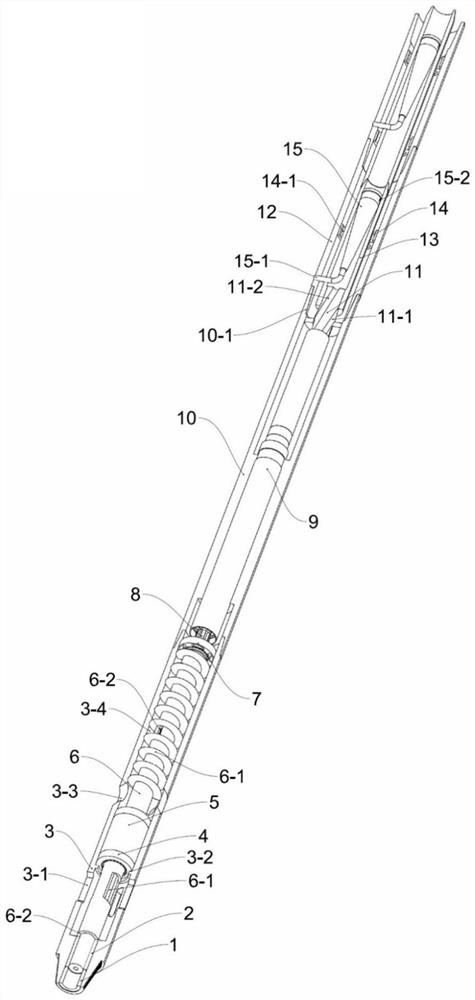
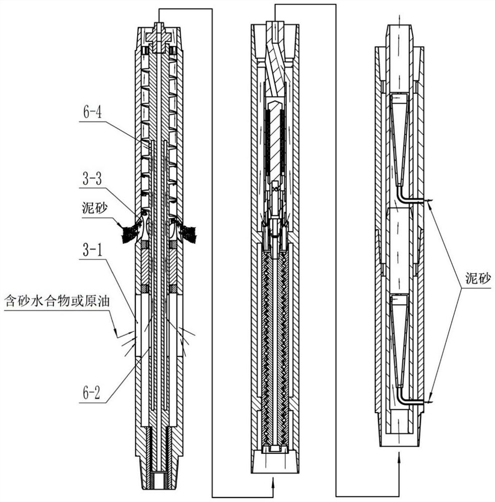
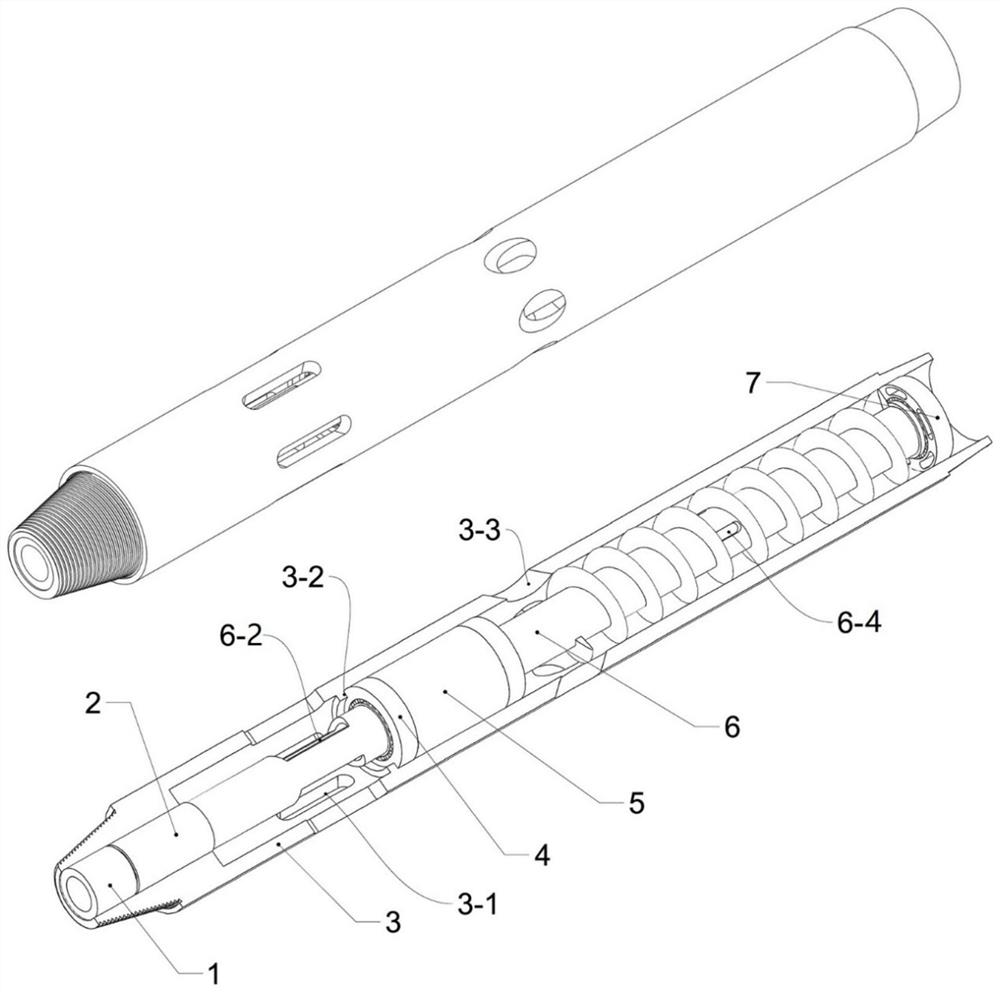
[0014] To sum up, in order to solve the serious problem of sand production in the current oil and gas hydrate production, a downhole separator that can separate mud and sand in real time is urgently needed to realize the downhole flow of high-sand content mixed fluid in the conventional oil or hydrate production process. In-situ real-time separation and backfill

Method used


Image

  • Underground hydraulically-driven spiral-rotational flow coupling tubular separator
  • Underground hydraulically-driven spiral-rotational flow coupling tubular separator
  • Underground hydraulically-driven spiral-rotational flow coupling tubular separator

Examples


Embodiment Construction

[0053] The present invention will be further described below in conjunction with accompanying drawing, protection scope of the present invention includes but not limited to following description:

[0054] Such as Figure 1 to Figure 10 As shown, a downhole hydraulically driven spiral-swirl coupled tubular separator is characterized in that it includes three parts: a spiral crushing and separating device, a hydraulic motor screw pump device, and a multi-stage swirling fine separating device;

[0055] The screw crushing and separating device is composed of a packing gland 1, a dynamic sealing packing 2, a spiral crushing and separating device shell 3, an axial positioning bearing 4, a sealing cylinder section 5, a separating screw 6, and an overflow bearing I7. The dynamic sealing packing 2 Installed at the lower end of the shell 3 of the spiral crushing and separating device, the packing gland 1 is connected to the lower end of the shell 3 of the spiral crushing and separating ...


PUM


Abstract

The invention discloses an underground hydraulically-driven spiral-rotational flow coupling tubular separator. The underground hydraulically-driven spiral-rotational flow coupling tubular separator comprises a spiral crushing and separating device, a hydraulic motor screw pump device and a multi-stage rotational flow fine separating device; the upper end and the lower end are connected with a drill rod, the upper end of the spiral crushing and separating device is connected with the hydraulic motor screw pump device, and the upper end of the hydraulic motor screw pump device is connected withthe multi-stage rotational flow fine separating device; the drilling fluid flowing in the innermost casing drives a hydraulic motor to rotate, drives a hydraulic motor screw pump to work, and furtherdrives a separation screw to rotate. The underground hydraulically-driven spiral-rotational flow coupling tubular separator has the characteristics of spiral and rotational flow separation coupling principle and self-powered underground separation, secondary crushing and cementation breaking of hydrate solid-phase particles can be realized, underground in-situ real-time multiple separation and backfilling of high-sand-content mixed fluid in conventional petroleum or hydrate recovery can also be realized, and the problems that when underground mixed fluid is recovered, sand content is high, friction resistance is large, lifting is difficult, and serious erosion and blocking are caused to a shaft, equipment and the like are well solved.

Description

technical field [0001] The invention relates to the field of oil and natural gas hydrate development, in particular to a downhole hydraulically driven spiral-swirl coupled tubular separator. Background technique [0002] At present, the proportion of oil and natural gas in global energy consumption still far exceeds that of other energy sources, and oil and natural gas are still the focus of the world's energy industry development strategy. [0003] At present, most of the light oil reservoirs that are relatively easy to be exploited in my country have been developed and mined, and the exploitation of heavy oil reservoir resources has become the main production source of most oil companies. At present, unconsolidated sandstone reservoirs are widely distributed and are the main heavy oil for oil and gas production in my country. One of the oil reservoirs. However, due to the serious sand production in unconsolidated sandstone reservoirs, the normal production of oil wells is g...

Claims


Application Information

Patent Timeline
Patent Type & Authority Applications(China)
IPC IPC(8): E21B43/38E21B43/40E21B43/01
CPCE21B43/01E21B43/38E21B43/385
Inventor 唐洋李泽良赵鹏王远倪申童熊浩宇王国荣王金忠赵金海何玉发沈哲民何胤
Owner SOUTHWEST PETROLEUM UNIV
Why Eureka
Try Eureka