Check patentability & draft patents in minutes with Patsnap Eureka AI!

SCR denitration system

A denitration and pipeline technology, applied in the field of SCR denitration system, can solve the problem of inappropriate denitration treatment, and achieve the effect of promoting the cooling effect

Active Publication Date: 2021-03-26
CHINA HUADIAN ENG +1
View PDF11 Cites 1 Cited by
  • Summary
  • Abstract
  • Description
  • Claims
  • Application Information

AI Technical Summary

Problems solved by technology

[0004] Therefore, the technical problem to be solved by the present invention is to overcome the defect that the existing medium-temperature SCR catalyst is not suitable for the denitrification treatment of the flue gas of the internal combustion engine generator set, thereby providing an SCR denitrification system

Method used


Image

  • SCR denitration system
  • SCR denitration system

Examples


Embodiment 1

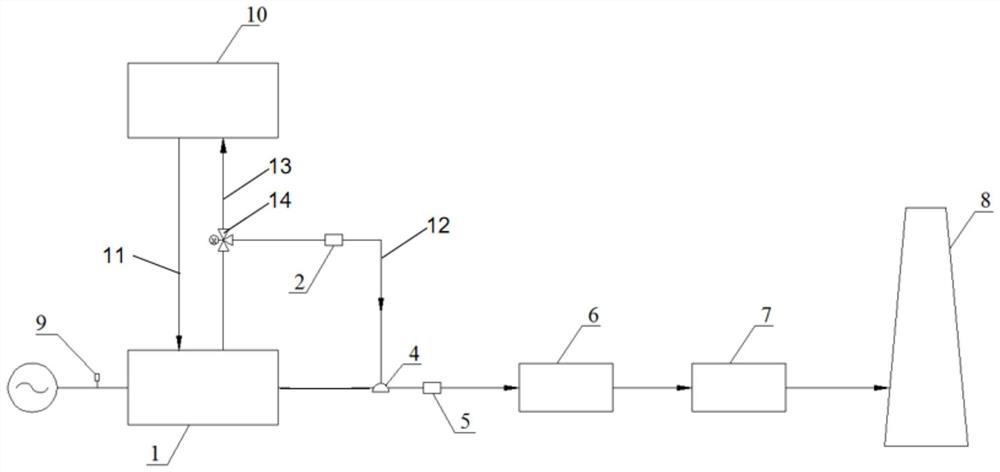
[0037] This embodiment provides an SCR denitrification system, including a cooling water tank 10, an internal combustion engine generator set 1, an SCR denitrification device 6, a spray unit 4, a flue gas hot water type lithium bromide machine 7, and a chimney 8. The internal combustion engine generator set 1 includes a smoke gas outlet, intercooled water inlet and intercooled water outlet, the SCR denitrification device 6 communicates with the flue gas outlet through a flue, the cooling water tank 10 communicates with the intercooled water inlet through a first pipeline 11, and the spray The shower unit 4 communicates with the intercooled water outlet through the second pipeline 12, the spray unit 4 is arranged in the flue, the SCR denitrification device 6, the flue gas hot water type lithium bromide machine 7 and the chimney 8 are connected in sequence , so that the flue gas after the denitrification reaction is completed enters the flue gas hot water type lithium bromide mac...

Embodiment 2

[0063] Such as figure 2 As shown, this embodiment provides an SCR denitrification system, which differs from the SCR denitrification system provided in Embodiment 1 only in that the SCR denitrification system does not include a second temperature sensor and a second control module, but includes:

[0064] Generating power testing device 8 is electrically connected with the internal combustion engine generator set 1;

[0065] The third control module (not shown in the figure), the third control module is electrically connected with the generating power testing device 8 and the communication valve 14, so as to control The opening and closing of the spray unit 4 .

[0066] Specifically, the generating power test device 8 is used to test the generating power of the internal combustion engine generator set 1, and the third control module is preset to obtain a generating power range corresponding to the temperature window of the medium-temperature SCR catalyst; When the above powe...


PUM


Abstract

The invention provides an SCR denitration system. The SCR denitration system comprises a heat dissipation water tank, an internal combustion engine generator set, an SCR denitration device and a spraying unit, wherein the internal combustion engine generator set comprises a flue gas outlet, an intercooling water inlet and an intercooling water outlet; the SCR denitration device communicates with the flue gas outlet through a flue; the heat dissipation water tank communicates with the intercooling water inlet through a first pipeline; and the spraying unit communicates with the intercooling water outlet through a second pipeline and is arranged in a flue. Intercooling water from the heat dissipation water tank firstly enters the internal combustion engine generator set to cool the internalcombustion engine generator set, so it is guaranteed that the internal combustion engine generator set works at an optimal temperature; and then, the intercooling water from the internal combustion engine generator set is sprayed into the flue through the spraying unit so as to cool the flue gas from the internal combustion engine generator set, so a medium-temperature SCR catalyst is suitable fordenitration treatment of the flue gas from the internal combustion engine generator set.

Description

technical field [0001] The invention relates to the technical field of flue gas denitrification, in particular to an SCR denitrification system. Background technique [0002] The internal combustion engine uses natural gas or fuel oil as fuel, and drives the generator set to generate electricity through combustion to generate high-grade electric energy. Internal combustion engines are most common with piston internal combustion engines. The piston-type internal combustion engine mixes fuel and air and burns it in its cylinder, and the heat energy released makes the cylinder generate high-temperature and high-pressure gas. The expansion of the gas pushes the piston to do work, and then the mechanical work is output through the crank connecting rod mechanism or other mechanisms to drive the driven machine to work. Since the piston internal combustion engine cannot achieve low-nitrogen combustion, the NOx emission mass concentration in the flue gas is relatively high, general...

Claims


Application Information

Patent Timeline
IPC IPC(8): B01D53/94B01D53/34B01D53/56
CPCB01D53/9431B01D53/9495B01D53/346B01D2258/01Y02T10/12
Inventor 李贞李建标徐静静江婷王晓海
Owner CHINA HUADIAN ENG
Features
  • R&D
  • Intellectual Property
  • Life Sciences
  • Materials
  • Tech Scout
  • Unparalleled Data Quality
  • Higher Quality Content
  • 60% Fewer Hallucinations
Learn More