Wheeled leg robot and driving method thereof

A technology of wheel-legged robots and thighs, which is applied in the fields of motor vehicles, transportation and packaging, etc. It can solve the problems of system power loss, small output torque of joint drive devices, partial overflow loss of pumping stations, etc.

Active Publication Date: 2021-03-26
北京理工大学重庆创新中心 +1
View PDF12 Cites 1 Cited by
  • Summary
  • Abstract
  • Description
  • Claims
  • Application Information

AI Technical Summary

Problems solved by technology

[0005] 1. In the hydraulic system using the servo valve control cylinder as the joint actuator of the wheel-leg robot, a centralized pump station is used as the power source. In order to maintain a constant system pressure, the pump station part needs to use an overflow valve for overflow to maintain a constant pressure. , in this way, there is always overflow loss in the pump station part, which brings about the power loss of the system
[0006] 2. The servo valve control cylinder achieves precise output force / speed control of the hydraulic cylinder through the throttling of the servo valve. There is a large throttling power loss, the transmission efficiency of the hydraulic system is low, and the effective energy utilization rate of the robot is low.
Generally, when the wheel-legged robot is running, the output torque of its joint drive device needs to overcome its own gravity and inertial force, so a larger torque is required at this time, and a hydraulic actuator is required to drive it, which can achieve a higher power density. However, when the wheel-legged robot is performing a gait to cross obstacles, the joint drive device only needs to overcome the weight of the legs at this time, so the output torque of the joint drive device required at this time is relatively small. If the servo valve is used to control For the cylinder actuator, a huge pressure difference will be generated at the valve port of the servo valve, resulting in a large throttling loss

Method used


Image

  • Wheeled leg robot and driving method thereof
  • Wheeled leg robot and driving method thereof
  • Wheeled leg robot and driving method thereof

Examples


Embodiment 1

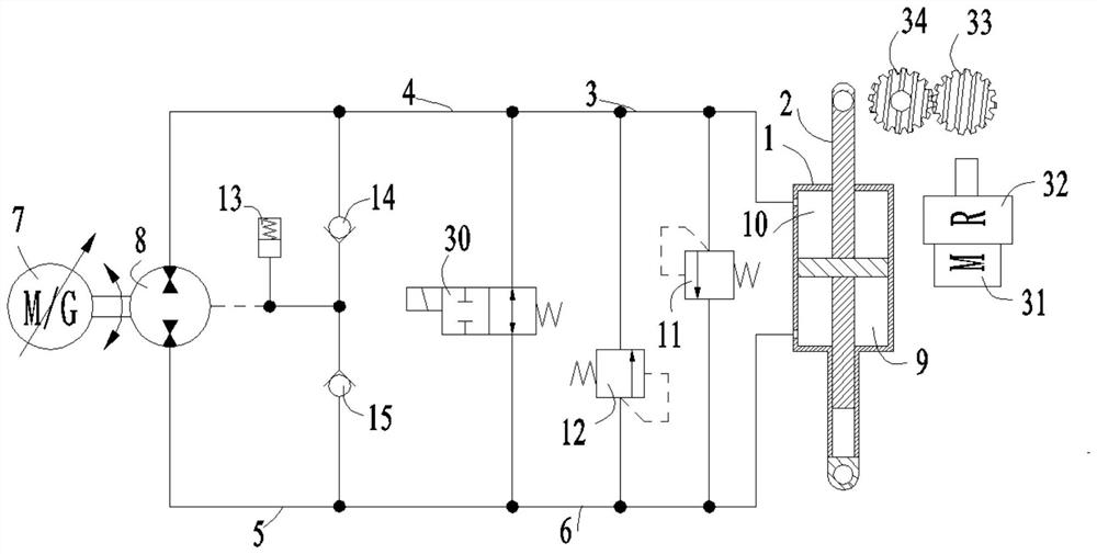
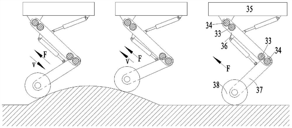
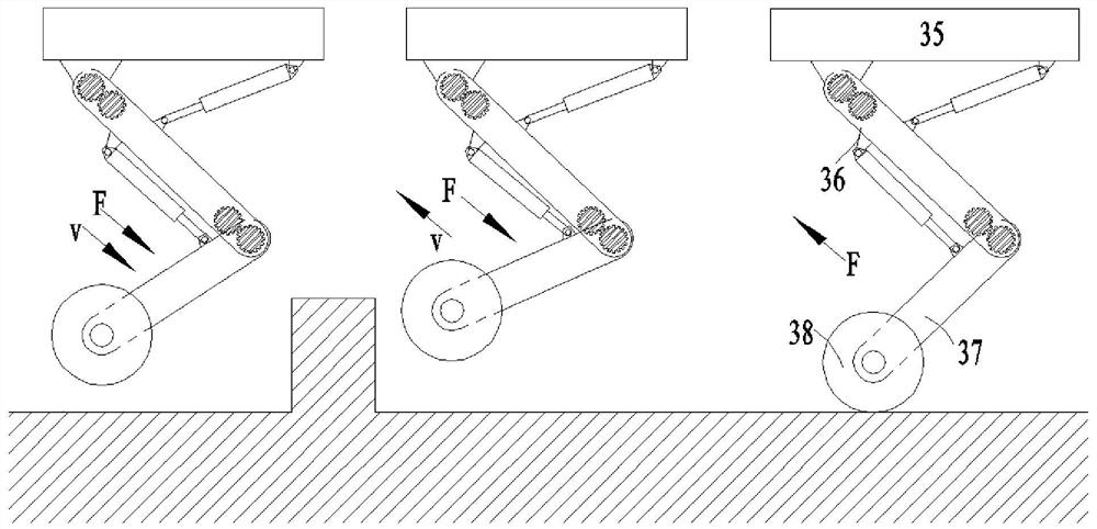
[0028] See attached Figure 1~3. A wheel-legged robot comprises a car body 35, a thigh 36, a calf 37, a wheel 38 and two hydraulic control systems; one end of the thigh 36 is hinged to the car body 35, and the other end of the thigh 36 is hinged to one end of the calf 37; the calf The other end of 37 is provided with a wheel 38; the hydraulic control system includes a hydraulic cylinder 1, a piston rod 2 and a motor gear control system; the hydraulic cylinder 1 is provided with a bearing chamber 9 and a non-bearing chamber 10; Bearing chamber 9 and non-bearing chamber 10; one hydraulic control system controls the angle between the car body 35 and the thigh 36 by controlling the elongation of the piston rod 2 relative to the hydraulic cylinder 1 or through the motor gear control system; the other hydraulic control system The control system controls the angle between the thigh 36 and the lower leg 37 by controlling the elongation of the piston rod 2 relative to the hydraulic cy...

Embodiment 2

[0030] See attached Figure 1~3 . On the basis of Embodiment 1, the hydraulic control system also includes a main oil circuit, a secondary oil circuit, a servo motor 7 and a hydraulic pump 8; the servo motor 7 is used to drive the hydraulic pump 8; the non-bearing chamber 10, The main oil circuit, the hydraulic pump 8, the secondary oil circuit and the bearing chamber 9 are connected in sequence; the elongation of the piston rod 2 relative to the hydraulic cylinder 1 changes with the change of the hydraulic oil capacity in the bearing chamber 9 and the non-bearing chamber 10 . It can be seen from the above structure that if the circuit formed by the non-bearing chamber 10, the main oil circuit, the hydraulic pump 8, the secondary oil circuit and the bearing chamber 9 is connected in sequence, the servo motor 7 will rotate forward, and the hydraulic oil in the bearing chamber 9 will be pumped by the hydraulic pump. 8 is sucked to the non-bearing cavity 10, the elongation of t...

Embodiment 3

[0038] See attached Figure 1~3 . A method for driving a wheel-legged robot, using the wheel-legged robot described in Embodiment 1, including an active vibration reduction step; the active vibration reduction step specifically includes: driving the wheel-legged robot to travel when the wheel 38 touches the ground and rotates; When the wheel-legged robot is running on a flat ground, there is no forced exchange of hydraulic oil between the bearing chamber 9 and the non-bearing chamber 10; the load force borne by the hydraulic cylinder 1 and the piston rod 2 has no fluctuation, and the car body 35 has no vibration. The relative elongation of piston rod 2 to hydraulic cylinder 1 remains constant, and the angle between car body 35 and thigh 36 and the angle between thigh 36 and shank 37 remain constant; When the ground is sloped, the load force borne by the hydraulic cylinder 1 and the piston rod 2 becomes larger, the hydraulic oil is forced to exchange between the bearing chambe...


PUM


Abstract

The invention discloses a wheeled leg robot and a driving method thereof, and belongs to the technical field of wheeled leg robots, the wheeled leg robot comprises a vehicle body, thighs, shanks, wheels and two hydraulic control systems; the hydraulic control system comprises a hydraulic cylinder, a piston rod and a motor gear control system; a bearing cavity and a non-bearing cavity are formed inthe hydraulic cylinder; the piston rod separates the bearing cavity from the non-bearing cavity; a hydraulic control system controls the extension of the piston rod relative to the hydraulic cylinderor controls the included angle between the vehicle body and the thigh through a motor gear control system; and the other hydraulic control system controls the extension of the piston rod relative tothe hydraulic cylinder or controls the included angle between the thigh and the shank through a motor gear control system. According to the wheeled leg robot and the driving method thereof, overflow loss and throttling loss are avoided, the system power is saved, the transmission efficiency of a hydraulic system is high, the energy utilization rate is high, the buffering performance is good, and the service life is long.

Description

technical field [0001] The invention belongs to the technical field of wheel-leg robots, and in particular relates to a wheel-leg robot and a driving method thereof. Background technique [0002] The wheel-legged robot refers to adding wheels to the end of the robot legs. This kind of robot fully combines the advantages of wheels and legs. pass in a structured environment. Compared with the legged robot, it has a faster traveling speed in the road environment, so the research on the wheel-legged robot has received more and more attention. [0003] At present, research on wheel-legged robots is mainly focused on small wheel-legged robot platforms. The robot body and load capacity are small, and the combination of motor and reducer can be used to drive the leg joints; for medium / large wheel-legged robots The drive of the leg joints is driven by a servo valve control cylinder. The servo valve is installed on the hydraulic cylinder, and the piston rod of the hydraulic cylinder...

Claims


Application Information

Patent Timeline
Patent Type & Authority Applications(China)
IPC IPC(8): B62D57/028
CPCB62D57/028
Inventor 胡小东徐彬秦也辰刘辉项昌乐杨海洋刘春桃
Owner 北京理工大学重庆创新中心
Why Eureka
Try Eureka