A biomass steam explosion device

A biomass and steam technology, applied in the separation of raw materials, etc., can solve the problems of high energy consumption, difficult cleaning, poor steam penetration, etc., and achieve the effect of increasing penetration, reducing difficulty, and uniform heating

Active Publication Date: 2022-05-03
上海汉禾生物新材料科技有限公司 +1
View PDF8 Cites 0 Cited by
  • Summary
  • Abstract
  • Description
  • Claims
  • Application Information

AI Technical Summary

Problems solved by technology

[0004] (1) The raw materials for steam explosion treatment are all kinds of plant fiber solid raw materials. The solid materials will be squeezed each other in the air explosion tank, which will seriously affect the penetration of steam in the material and affect the gas explosion effect of the material. Therefore, the existing steam explosion The design of the steam-introduced piping inside the device generally has poor steam penetration. The steam at the bottom material accumulation cannot evenly penetrate, so the temperature of the bottom material cannot reach the appropriate gas explosion temperature, and the gas explosion effect is very unsatisfactory. In this case, it is necessary to design a steam pipeline structure in which steam can penetrate evenly in the internal material;
[0005] (2) During the process of steam explosion treatment, the raw materials at the inner edge are squeezed against each other, so that the central steam cannot pass through efficiently and fully, so that the raw materials at the edge cannot reach the appropriate gas explosion temperature. In addition, the raw materials at the outermost edge are likely to be Extruded and attached to the inner wall of the device, resulting in difficult cleaning problems. In addition, the installation of additional turning and cleaning devices requires the installation of additional electrical equipment. This method will cause high energy consumption and is not advisable.

Method used


Image

  • A biomass steam explosion device
  • A biomass steam explosion device
  • A biomass steam explosion device

Examples


Embodiment Construction

[0031] The following will clearly and completely describe the technical solutions in the embodiments of the present invention with reference to the accompanying drawings in the embodiments of the present invention. Obviously, the described embodiments are only some, not all, embodiments of the present invention. Based on the embodiments of the present invention, all other embodiments obtained by persons of ordinary skill in the art without making creative efforts belong to the protection scope of the present invention.

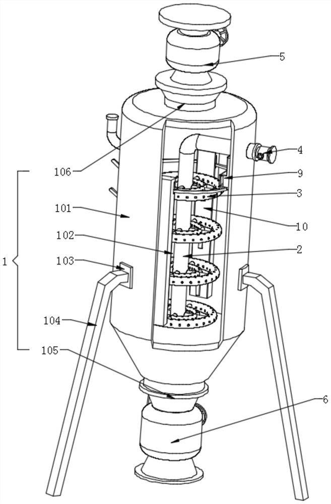
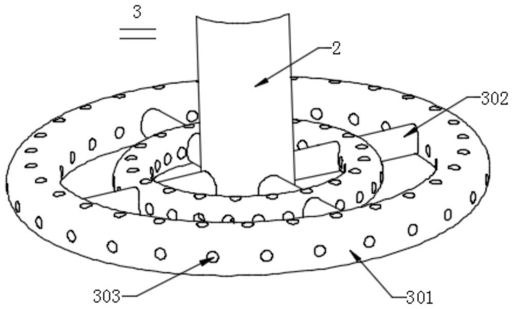
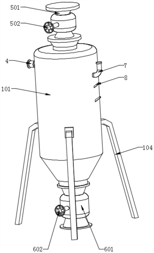
[0032] Please also refer to Figure 1-7 , figure 1 It is a schematic diagram of a front view three-dimensional structure of a biomass steam explosion device in an embodiment of the present invention, figure 2 for figure 1 The schematic diagram of the three-dimensional structure of the steam pipeline in the tank shown in the embodiment, image 3 for figure 1 The schematic diagram of the rear view three-dimensional structure shown in the embodiment, Figur...


PUM


Abstract

A biomass steam explosion device provided by the present invention includes a steam explosion device, an internal steam main pipeline, a steam pipeline in a tank, a steam-driven linkage device, a material turning device and a connecting ring. The internal steam main pipeline is fixedly installed on Inside the steam explosion device, the steam pipeline in the tank is uniformly fixed and installed on the outer surface of the internal steam main pipeline, and the steam pipeline in the tank is fixed and installed inside the steam explosion device. The steam-operated linkage device is fixedly installed on the inner top of the steam explosion device, the material turning device is evenly fixed on the inner wall of the steam explosion device, and the connecting rings respectively move through the steam-operated linkage device and the material turning device. Device; the invention can ensure that the steam can pass through the material evenly, increase the penetration of the material accumulated at the bottom and the edge, and at the same time prevent the material from adhering to the inner wall, and finally do not need additional electric equipment to realize the material turning work.

Description

technical field [0001] The invention relates to the technical field of biorefinery, in particular to a biomass steam explosion device. Background technique [0002] Steam explosion pretreatment equipment is especially used for steam explosion devices that can evenly feed steam to ensure uniform temperature of materials inside the equipment. Steam explosion pretreatment technology plays a very important part in biorefinery production. Plant fibers undergo high-intensity blasting Treatment can destroy its dense fiber structure, which is beneficial to the action of microorganisms and enzymes in the subsequent biorefinery, and ensure that the steam is stably and evenly introduced into the steam during the steam explosion process, ensuring that the steam can circulate normally in the material and thus ensure the quality of the material. Accurate and effective response to gas explosion is particularly important; [0003] However, steam explosion treatment has the following disadv...

Claims


Application Information

Patent Timeline
Patent Type & Authority Patents(China)
IPC IPC(8): D21B1/36
CPCD21B1/36
Inventor 李栋杰高郁天陶程程
Owner 上海汉禾生物新材料科技有限公司
Why Eureka
Try Eureka