Continuous sucker rod operation vehicle and method

A sucker rod and working vehicle technology, which is applied to drill pipes, earth-moving drilling, drilling equipment, etc., can solve the problems of easy damage to continuous sucker rods, inconvenient transportation and scattered equipment, etc.

Active Publication Date: 2021-03-26
华信唐山石油装备有限公司
View PDF7 Cites 14 Cited by
  • Summary
  • Abstract
  • Description
  • Claims
  • Application Information

AI Technical Summary

Problems solved by technology

[0003] At the present stage, the functions and operating techniques of the continuous sucker rod special operation equipment used by major domestic oil fields and oil service companies are relatively simple, and there are the following defects: 1) The operation is complicated and requires manual assistance, and the labor intensity is high; 2) Lifting devices are needed to assist the operation, and the renting of equipment increases the operating cost; 3) The continuous sucker rod pipe arrangement device needs to be adjusted manually, and there are potential safety hazards for personnel to move around the rotating parts for a long time; 4) Electric drive is mostly used, and the power supply requirements for the well site 5) Because there are many electric drive and electric control equipment and they are close to the wellhead, safety management requires the equipment to be explosion-proof, which increases the cost of equipment procurement; 6) Continuous sucker rods rely on counterweight rods and Drum with well entry and exit
The weight of the counterweight rod and the torque of the drum are limited. When the continuous sucker rod is stuck, the continuous sucker rod cannot be pulled out of the wellhead, and the hovering continuous sucker rod has the risk of slipping; 7) When the carbon fiber continuous sucker rod is used together, the equipment is easy to damage Continuous sucker rod; 8) Scattered equipment and inconvenient transportation

Method used


Image

  • Continuous sucker rod operation vehicle and method
  • Continuous sucker rod operation vehicle and method
  • Continuous sucker rod operation vehicle and method

Examples


Embodiment Construction

[0054] Below in conjunction with accompanying drawing and embodiment the present invention will be further described:

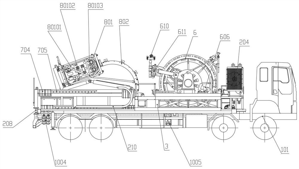
[0055] Refer to attached Figure 1~11 , a continuous sucker rod operation vehicle, including power system 1, control system 2, sub-frame beam 3, side rear protection 4, pipeline shield 5, sucker rod drum 6, sliding platform 7, continuous sucker rod injection Head assembly 8, rod traction assembly 9, supporting accessories assembly 10, continuous sucker rod 11.

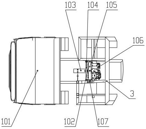
[0056] The power system 1 includes a chassis vehicle 101 as a source of transportation and power, a transmission shaft 102 connected to the power take-off of the chassis vehicle, a transmission shaft shield 103 with a C-shaped structure, a shield bracket 104 with a door-shaped cross-bar structure, Transmission case 105, the hydraulic pump 106 that converts mechanical energy into hydraulic power; Wherein the transmission shaft 102, the transfer case 105 and the hydraulic pump are connected in series, an...


PUM


Abstract

The invention relates to a continuous sucker rod operation vehicle and method, and belongs to the technical field of petroleum machinery. According to the technical scheme, the continuous sucker rod operation vehicle comprises a power system, a control system, an auxiliary frame beam, a side rear protector, a pipeline shield, a sucker rod roller, a sliding platform, a continuous sucker rod injection head assembly, a rod traction assembly, a matched accessory assembly and a continuous sucker rod. According to the continuous sucker rod operation vehicle, an operation vehicle type is adopted, thetrafficability of a cross-country type chassis vehicle is good, and the cross-country type chassis vehicle can adapt to various severe road conditions and well sites and is convenient to move and transport; a chassis vehicle engine power driving system is adopted for operation, so that the economy and stability are good; the operation vehicle has the advantages of the compact structure and complete function and can be operated independently; the sucker rod roller has two safety protection measures of speed reducer braking and hydraulic release type braking, so that accidents caused by hydraulic failure are avoided; the injection head has large lifting force and injection force, so that more complex underground conditions can be solved; and two wells can be operated at a time, so that theefficiency is improved, and economic benefits are obtained.

Description

technical field [0001] The invention relates to a continuous sucker rod operating vehicle and a method thereof, belonging to the technical field of petroleum machinery. Background technique [0002] Continuous sucker rod is a new type of composite material oilfield equipment, mainly used in rod pump wells in oilfields. It has excellent characteristics such as good flexibility and coilability, light weight, energy saving, corrosion resistance, fatigue resistance, high temperature resistance, and high strength. Therefore, it has won widely used. When the continuous sucker rod is used, it needs to be equipped with special operation equipment. The continuous sucker rod operation vehicle is a special equipment that can inject or pull out the continuous sucker rod into the oil well. The operation vehicle is equipped with power system, console, sucker rod drum, guide device, technical device and other equipment to realize the operation function. Continuous sucker rod has been vig...

Claims


Application Information

Patent Timeline
Patent Type & Authority Applications(China)
IPC IPC(8): E21B19/14
CPCE21B19/14E21B19/146
Inventor 陈春雷宋亮张书军张宝龙侯玉文刘传滨田国徽陈付坤
Owner 华信唐山石油装备有限公司
Why Eureka
Try Eureka