Lens refractive index measuring device and measuring method thereof

A measuring device and refractive index technology, applied in the field of optical measurement, can solve problems such as complex operation, difficult detection, and high difficulty, and achieve the effect of simple operation and fast detection

Pending Publication Date: 2021-03-26
宁波法里奥光学科技发展有限公司
View PDF0 Cites 2 Cited by
  • Summary
  • Abstract
  • Description
  • Claims
  • Application Information

AI Technical Summary

Problems solved by technology

[0003] At present, there are mainly two detection methods for measuring the refractive index of finished lenses. One is to perform reverse calculation based on the focal power formula, that is, to use mechanical precision measurement methods to measure the curvature of the upper and lower surfaces, the central thickness, and the focal power of the lens. The focal length company calculates the refractive index of its test wavelength. This method is complicated and difficult to guarantee the measurement accuracy, and it is not suitable for the measurement of aspheric lenses; another method is to change t

Method used


Image

  • Lens refractive index measuring device and measuring method thereof
  • Lens refractive index measuring device and measuring method thereof
  • Lens refractive index measuring device and measuring method thereof

Examples


Embodiment 1

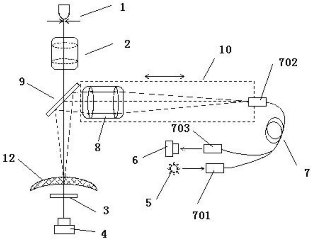
[0029] The lens refractive index measuring device of the present invention includes a diopter measurement module, a confocal reflection measurement module and a measured lens.

[0030] The diopter measurement module includes a first light source module 1 , a first collimator lens 2 , a Hartmann diaphragm 3 and a first photodetector 4 . The first light source module 1 includes a first light source and a first hole, and a light-transmitting hole is provided on the side of the first hole near the light-emitting surface of the first light source; The light emitted by the light source is emitted after passing through the light transmission hole. The first light source is a monochromatic LED light source with a spectral width greater than 10 nanometers and less than 50 nanometers. The diameter of the light transmission hole is less than 0.5 mm, preferably less than 0.2 mm; the distance between the light transmission hole and the first light source is less than 0.5 mm; the focal len...

Embodiment 2

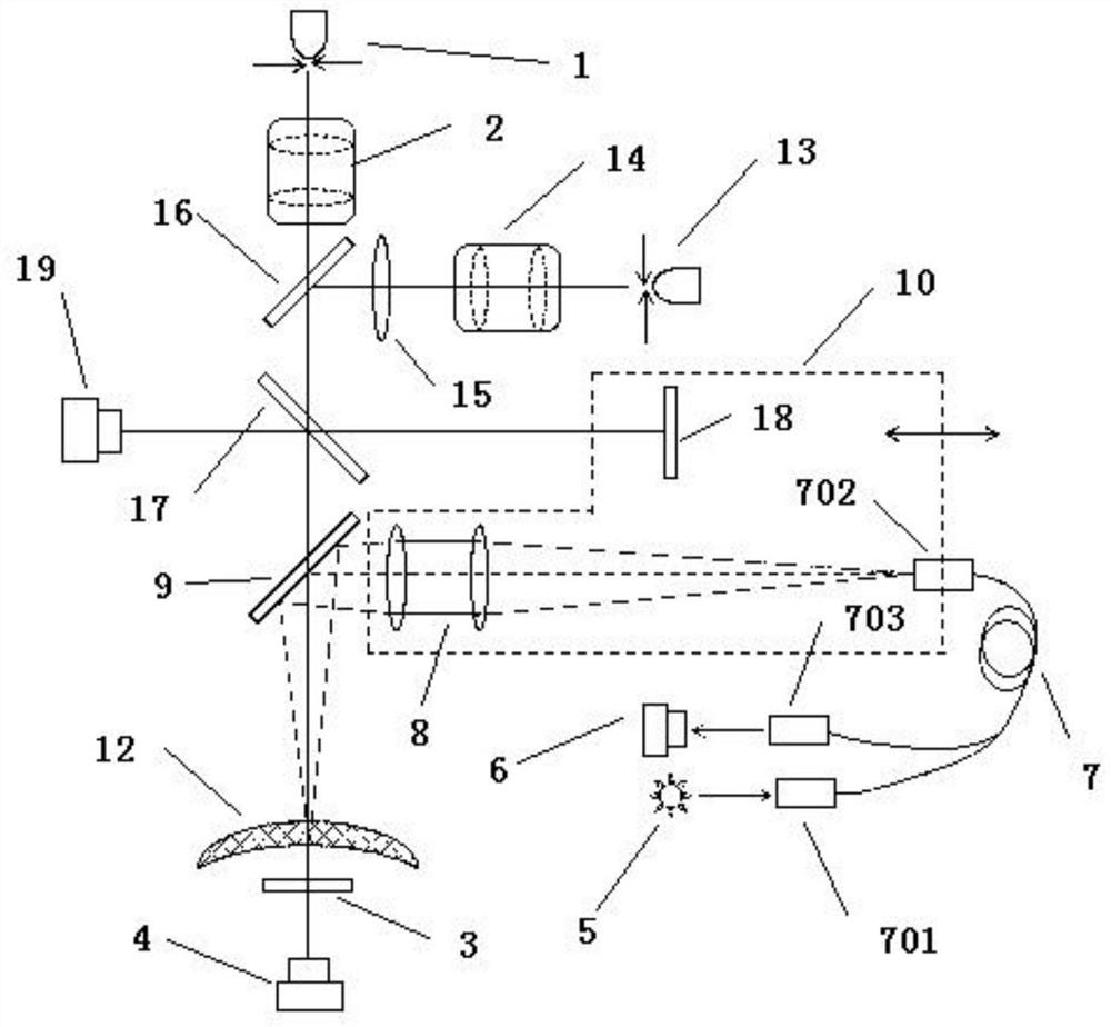
[0044] The lens refraction index measurement device of the present invention includes a diopter measurement module, a confocal reflection measurement module, an optical thickness measurement module and a measured lens.

[0045] The diopter measurement module includes a first light source module 1 , a first collimator lens 2 , a Hartmann diaphragm 3 and a first photodetector 4 . The first light source module 1 includes a first light source and a first hole, and a light-transmitting hole is provided on the side of the first hole near the light-emitting surface of the first light source; The light emitted by the light source is emitted after passing through the light transmission hole. The first light source is a monochromatic LED light source with a spectral width greater than 10 nanometers and less than 50 nanometers. The diameter of the light transmission hole is less than 0.5 mm, preferably less than 0.2 mm; the distance between the light transmission hole and the first ligh...


PUM

PropertyMeasurementUnit
Spectral widthaaaaaaaaaa
Diameteraaaaaaaaaa
Diameteraaaaaaaaaa

Abstract

The invention discloses a lens refractive index measuring device which comprises a diopter measuring module, a confocal reflection measuring module and a measured lens. The diopter measuring module isused for detecting the diopter of a measured lens, the confocal reflection measuring module is used for detecting the confocal reflection positions of the upper surface and the lower surface of the measured lens. According to the measuring device, the lens refractive index of the measured lens can be obtained, the lens does not need to be damaged, operation is easy, and detection is rapid; and the device is suitable for refractive index measurement of common lenses, aspheric lenses, cylindrical lenses and other irregular surface lenses. The method for measuring the refractive index of the lens is simple to operate, rapid in detection and high in measurement precision.

Description

technical field [0001] The invention relates to the technical field of optical measurement, in particular to a lens refractive index measurement device and a measurement method thereof. Background technique [0002] The refractive index parameter is an important parameter index of the optical lens. In order to ensure the good imaging quality of the optical system, it is necessary to accurately measure the refractive index of the optical material. At present, the high-precision measurement of the refractive index of the optical glass material is carried out by the minimum deflection angle method. The minimum deflection angle method has high precision, a large wavelength range, and is a direct measurement. However, the premise of the minimum deflection angle test method is that a prism needs to be made for light refraction, and the angle of the prism needs to be accurately tested. Such a prism is difficult to manufacture. , the cycle is long; in addition, this method cannot te...

Claims


Application Information

Patent Timeline
IPC IPC(8): G01M11/02G01N21/41G01N21/45
CPCG01M11/0235G01M11/0207G01N21/41G01N21/45
Inventor 刘义兵孙昭刘力威
Owner 宁波法里奥光学科技发展有限公司
Why Eureka
Try Eureka