
Multi-beam transceiving bistatic optical system

A technology of optical system and telecentric optical system, which is applied in the field of multi-beam receiving and displacing optical system, can solve problems such as difficult three-dimensional surveying and mapping, and achieve the effects of flexible beam arrangement design, high beam splitting efficiency, and reduced complexity

Active Publication Date: 2021-03-26
BEIJING RES INST OF TELEMETRY +1
View PDF2 Cites 1 Cited by
  • Summary
  • Abstract
  • Description
  • Claims
  • Application Information

AI Technical Summary

Problems solved by technology

[0005] In order to solve the difficult problem of large field of view and high-density three-dimensional surveying and mapping, the present invention proposes the matching technology of diffractive light splitting and transceiving optical fibers, and solves the beam splitting requirements of 64 high-efficiency laser beams through the DOE design of diffractive optical devices to realize multi-beam The high-precision matching of the laser emitting field of view and the receiving field of view enables multi-beam high-resolution laser three-dimensional detection to obtain high-precision and accurate information; through the design of the optical fiber surface array and the design of the telecentric optical system, the emission can be realized Strict matching technology with the receiving field of view, taking into account the large field of view and high sampling density, reducing system power consumption and weight, and reducing system complexity

Method used


Image

  • Multi-beam transceiving bistatic optical system
  • Multi-beam transceiving bistatic optical system
  • Multi-beam transceiving bistatic optical system

Examples


Embodiment 1

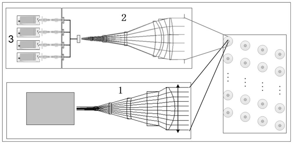
[0040] Such as figure 1 As shown, a multi-beam transceiving heterogeneous optical system includes a laser beam splitting transmitter module 1, an echo signal transmission module 2 arranged on one side of the laser beam splitter transmitter module 1, and an echo signal transmission module 2 electrically connected to the echo signal transmission module 2. wave signal receiving module 3;

[0041]The laser beam splitting transmitter module 1 is used to emit laser light and perform beam expansion and compression to split the beam into multi-beam laser output. The echo signal transmission module 2 is used to receive the echo signal generated by the multi-beam laser reflected by the target and couple it to the corresponding optical fiber array. Multiple beams of echo signals are output on the end face of the optical fiber, and the echo signals correspond to the multiple beams of laser light one by one. The echo signal receiving module 3 is used to receive the multiple beams of echo s...

Embodiment 2

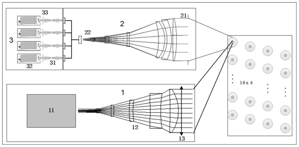
[0043] Such as figure 2 As shown, a multi-beam transceiving heterogeneous optical system includes a laser beam splitting transmitter module 1, an echo signal transmission module 2 arranged on one side of the laser beam splitter transmitter module 1, and an echo signal transmission module 2 electrically connected to the echo signal transmission module 2. wave signal receiving module 3;

[0044] The laser beam splitting transmitter module 1 is used to emit laser light and perform beam expansion and compression to split the beam into multi-beam laser output. The echo signal transmission module 2 is used to receive the echo signal generated by the multi-beam laser reflected by the target and couple it to the corresponding optical fiber array. Multiple beams of echo signals are output on the end face of the optical fiber, and the echo signals correspond to the multiple beams of laser light one by one. The echo signal receiving module 3 is used to receive the multiple beams of echo...

Embodiment 3

[0056] Such as figure 2 As shown, a multi-beam transceiving heterogeneous optical system includes a laser beam splitting transmitter module 1, an echo signal transmission module 2 arranged on one side of the laser beam splitter transmitter module 1, and an echo signal transmission module 2 electrically connected to the echo signal transmission module 2. wave signal receiving module 3;

[0057] The laser beam splitting transmitter module 1 is used to emit laser light and perform beam expansion and compression to split the beam into multi-beam laser output. The echo signal transmission module 2 is used to receive the echo signal generated by the multi-beam laser reflected by the target and couple it to the corresponding optical fiber array. Multiple beams of echo signals are output on the end face of the optical fiber, and the echo signals correspond to the multiple beams of laser light one by one. The echo signal receiving module 3 is used to receive the multiple beams of echo...


PUM

PropertyMeasurementUnit
diameteraaaaaaaaaa
diameteraaaaaaaaaa

Abstract

The invention provides a multi-beam transceiving bistatic optical system, which comprises a laser beam splitting transmitting module, an echo signal transmission module and an echo signal receiving module. After a laser of the laser beam splitting transmitting module emits light, a laser beam expander expands laser beams, and a diffraction beam splitting module DOE divides the laser beams into 64laser beams for dot matrix transmission; after being reflected by a target, emergent laser is received by a telescope of the echo signal transmission module and coupled into a corresponding optical fiber array, and echo signals pass through the optical fiber array, an optical filter of the echo signal receiving module and the double-telecentric optical system and then are transmitted to a photosensitive surface corresponding to the array detector. The invention provides a diffraction light splitting and transceiving bistatic optical fiber matching technology, which solves the beam splitting requirement of high-efficiency 64 beams of laser through the DOE design of a diffraction optical device. Through the arrangement design of the optical fiber area array and the design of the telecentricoptical system, the strict matching technology of a transmitting view field and a receiving view field can be achieved, and large-view-field and high-density laser three-dimensional detection is completed.

Description

technical field [0001] The invention relates to the technical field, in particular to a multi-beam transceiving and dislocation optical system. Background technique [0002] LiDAR has a wide range of applications, involving many disciplines, and has broad application prospects both in military and civilian applications. In military aspects: Lidar can be used for guidance and navigation of cruise missiles, ranging systems, for low-flying target tracking measurements, for target flight attitude measurement, detection of chemical, biological warfare agents, and underwater positioning and communication. On the civilian side: Lidar can be used in atmospheric remote sensing and atmospheric measurement, measurement of atmospheric ozone, hazard forecasting in industrial production, surveying and mapping and geodesy, vehicle collision avoidance, robot vision, non-destructive testing and medical diagnosis and other fields. LiDAR technology has achieved remarkable research and applica...

Claims


Application Information

Patent Timeline
Patent Type & Authority Applications(China)
IPC IPC(8): G01S7/481
CPCG01S7/4818G01S7/4817Y02A90/10
Inventor 梅艳鹏潘超赵一鸣刘宇哲边吉韩晓爽赵艳
Owner BEIJING RES INST OF TELEMETRY
Learn More