Delay line calibration circuit for FPGA type time-to-digital converter
A technology for calibrating circuits and time-to-digital, applied in time-to-digital converters, devices for measuring time intervals, measurement of electrical unknown time intervals, etc. It can solve the problems of poor portability of calibration circuits and limit calibration accuracy, and improve TDC measurement accuracy. , Reduce the influence of temperature/voltage changes, and improve the effect of real-time performance
- Summary
- Abstract
- Description
- Claims
- Application Information
AI Technical Summary
Problems solved by technology
Method used
Image
Examples
Embodiment 1
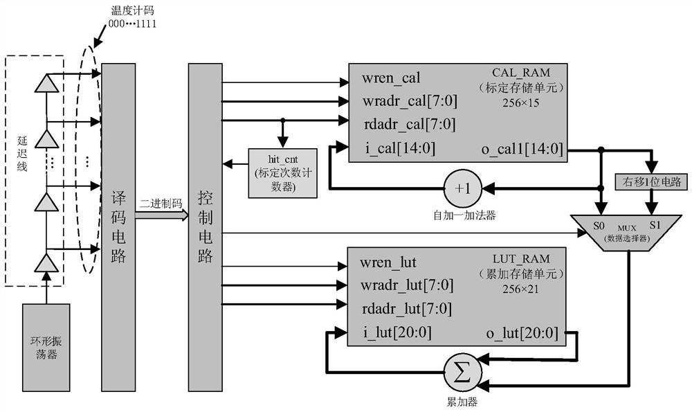
[0032] Embodiments of the present invention provide a delay line calibration circuit for FPGA-type time-to-digital converters, see Figure 1-Figure 7 , the circuit consists of:
[0033] 1. The delay line calibration circuit in the embodiment of the present invention is composed of a ring oscillator circuit, a control circuit, CAL_RAM and LUT_RAM storage units. The ring oscillator circuit is controlled by a reset signal to generate a random pulse signal for calibration. The control circuit controls the reading and writing of CAL_RAM and LUT_RAM through the finite state machine (FSM), and completes the calibration of the delay line and the accumulation of the count value. The CAL_RAM and LUT_RAM circuits are implemented by calling the Block RAM IP core. In the calibration state, CAL_RAM is used to store the number of jumps at each delay unit in the delay line; in the accumulation state, LUT_RAM is used to store the accumulated value of the number of jumps.
[0034] 2. In the ...
Embodiment 2
[0038] Combine below Figure 1-Figure 7 The scheme in Example 1 is further introduced, see the following description for details:
[0039] The delay of each delay unit in the delay line needs to be calibrated. Online real-time calibration can obtain more realistic delay information and reduce the impact of temperature / voltage changes on FPGA-type TDC measurement accuracy. The calibration methods of the delay line type TDC mainly include the average calibration method and the bit-by-bit calibration method. The system response time of the average calibration method is fast, and the delay line can be calibrated quickly, but this method can only calculate the average delay of the delay unit. When the linearity of the delay line is poor, this method cannot correct the delay unit. Calibrate one by one to increase the measurement error. Therefore, an embodiment of the present invention designs a calibration circuit to perform bit-by-bit calibration on the delay unit.
[0040] 1. ...
PUM
 Abstract
Description
Claims
Application Information
 - R&D
- Intellectual Property
- Life Sciences
- Materials
- Tech Scout
- Unparalleled Data Quality
- Higher Quality Content
- 60% Fewer Hallucinations
Browse by: Latest US Patents, China's latest patents, Technical Efficacy Thesaurus, Application Domain, Technology Topic, Popular Technical Reports.
© 2025 PatSnap. All rights reserved.Legal|Privacy policy|Modern Slavery Act Transparency Statement|Sitemap|About US| Contact US: help@patsnap.com


