Drying device for producing dried flowers

A drying device and drying flower technology, applied in drying, drying machine, drying gas arrangement, etc., can solve the problems of increasing the production cost of dried flowers, failure to recycle, uneven heating, etc., to improve the heating and drying effect, Reduce energy consumption and improve heating effect

Inactive Publication Date: 2021-04-02
颍上县红绿园家庭农场有限公司
View PDF1 Cites 2 Cited by
  • Summary
  • Abstract
  • Description
  • Claims
  • Application Information

AI Technical Summary

Problems solved by technology

[0003] The Chinese patent with the patent number CN201810780189.9 in the prior art discloses a dryer for the production of dried flowers, including: a body, a feeding hopper, and a machine door. The bottom of the body is connected to the organic door through a hinge. The top of the machine body is provided with a feeding hopper, one side of the feeding hopper is provided with a rotating motor, one side of the rotating motor is provided with a support, and a hot air blower is provided on the support, a drying bucket is provided in the body, and the drying A filter layer is arranged on the outside of the drying barrel, and a cover plate is arranged on the top of the drying barrel, and the cover plate is connected to the rotating motor through a motor shaft. The bottom is provided with a discharge port

Method used


Image

  • Drying device for producing dried flowers
  • Drying device for producing dried flowers
  • Drying device for producing dried flowers

Examples


Embodiment 1

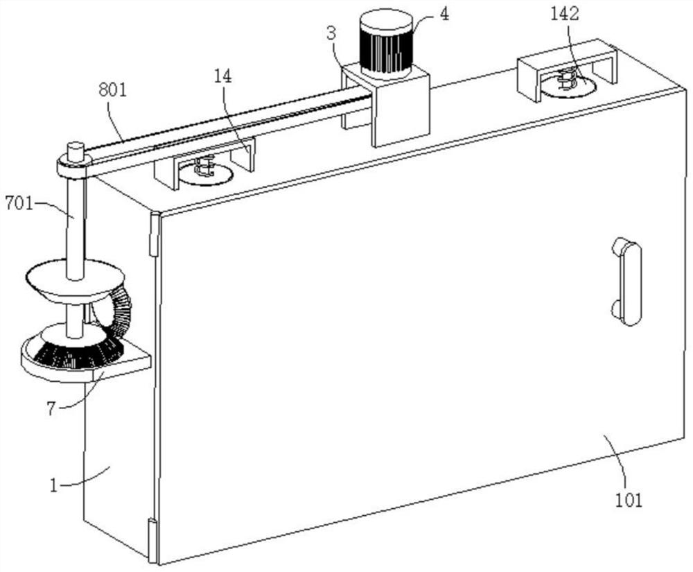
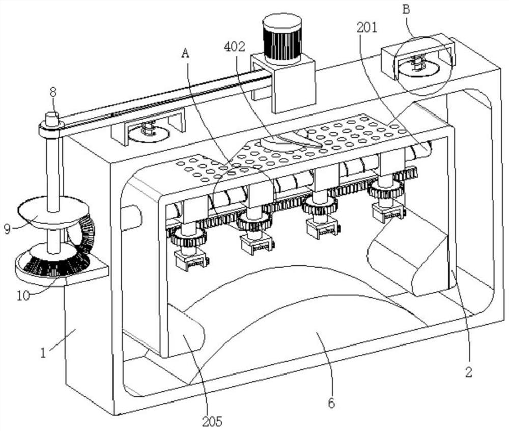
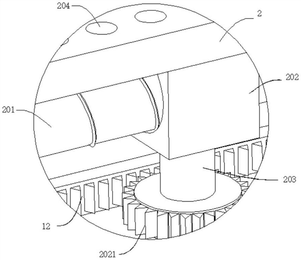
[0034] refer to figure 1 , figure 2 , image 3 and Figure 5 , a drying device for producing dried flowers, comprising a box body 1, the outer wall of the box body 1 is connected with a box door 101 through a hinge, the inner wall of the box body 1 is fixedly connected with a casing 2, and the top of the casing 2 is dug with evenly distributed The circulation hole 204, the inner wall of the housing 2 is connected with a threaded rod 201, the outer wall of the threaded rod 201 is threaded with a moving sleeve 202, the bottom wall of the moving sleeve 202 is connected with a connecting rod 203, and the end of the connecting rod 203 is far away from the moving sleeve 202 The clamping assembly is connected, the top of the box body 1 is connected to the support base 3, the outer wall of the support base 3 is connected to the motor 4, the output end of the motor 4 is connected to the rotating shaft, and the end of the rotating shaft away from the motor 4 passes through the suppor...

Embodiment 2

[0038] refer to figure 1 , figure 2 , image 3 and Figure 5 , a drying device for producing dried flowers, comprising a box body 1, the outer wall of the box body 1 is connected with a box door 101 through a hinge, the inner wall of the box body 1 is fixedly connected with a casing 2, and the top of the casing 2 is dug with evenly distributed The circulation hole 204, the inner wall of the housing 2 is connected with a threaded rod 201, the outer wall of the threaded rod 201 is threaded with a moving sleeve 202, the bottom wall of the moving sleeve 202 is connected with a connecting rod 203, and the end of the connecting rod 203 is far away from the moving sleeve 202 The clamping assembly is connected, the top of the box body 1 is connected to the support base 3, the outer wall of the support base 3 is connected to the motor 4, the output end of the motor 4 is connected to the rotating shaft, and the end of the rotating shaft away from the motor 4 passes through the suppor...

Embodiment 3

[0043] refer to figure 1 , figure 2 , image 3 , Figure 5 and Figure 6 , a drying device for producing dried flowers, which is basically the same as that of Embodiment 2, furthermore, the outer wall of the box body 1 is connected with a support plate 7, and the support plate 7 is connected with a rotating rod 701 through the first bearing in rotation, and the rotating rod 701 and the outer wall of the rotating shaft 401 are connected with a matching synchronous wheel 8 , and a synchronous belt 801 is connected between the two synchronous wheels 8 .

[0044] Two first bevel gears 9 and a second bevel gear 10 are respectively connected to the outer wall of the rotating rod 701, the second bevel gear 10 is placed below the first bevel gear 9, and both the first bevel gear 9 and the second bevel gear 10 are meshed A third bevel gear 11 is connected, and the third bevel gear 11 is connected with the threaded rod 201 .

[0045] Both the first bevel gear 9 and the second beve...


PUM


Abstract

The invention discloses a drying device for producing dried flowers, and belongs to the technical field of dried flower production. The drying device for producing the dried flowers comprises a box body, wherein the outer wall of the box body is connected with a box door through hinges, the inner wall of the box body is fixedly connected with a shell, circulation holes which are evenly distributedare dug in the top of the shell, the inner wall of the shell is connected with a threaded rod, the outer wall of the threaded rod is connected with movable sleeves in a threaded mode, and the bottomwalls of the movable sleeves are connected with connecting rods. A clamping assembly is connected to the end, far away from the corresponding movable sleeve, of each connecting rod, the top of the boxbody is connected with a supporting base, the outer wall of the supporting base is connected with a motor, the output end of the motor is connected with a rotating shaft, the end, far away from the motor, of the rotating shaft penetrates through the supporting base and is connected with a rotary shaft, the rotary shaft penetrates through the box body and extends inwards, and the outer wall of therotary shaft is connected with a heating piece and a rotary base. According to the drying device, the heating effect of the device on flowers can be improved advantageously, heating can be uniform, the energy consumption is reduced through circulating flow of the hot air, and then the production cost of the dried flowers is reduced.

Description

technical field [0001] The invention relates to the technical field of dried flower production, in particular to a drying device for producing dried flower. Background technique [0002] With the improvement of the quality of life and living standards of modern people, people often buy flowers to decorate their homes or offices, which can enrich indoor colors or convey specific emotions. However, due to the short storage time of flowers, there has been a trend of using dried flowers instead of fresh flowers for interior decoration. Dried flowers refer to the flowers made by using drying equipment or desiccant to quickly dehydrate the flowers. This kind of flowers can maintain the original color and shape of the flowers for a long time. Dried flowers are full of modern abstract decorative beauty, and are often used as fresh flowers. Substitute for all types of craft decoration. [0003] The Chinese patent with the patent number CN201810780189.9 in the prior art discloses a d...

Claims


Application Information

Patent Timeline
IPC IPC(8): F26B11/18F26B21/00F26B25/00F26B25/12F26B25/18
CPCF26B11/18F26B21/001F26B25/003F26B25/12F26B25/18
Inventor 方小燕徐兰华汪新菊徐兰青
Owner 颍上县红绿园家庭农场有限公司
Why Eureka
Try Eureka