
Indirect time of flight range calculation apparatus and method of calculating a phase angle in accordance with an indirect time of flight range calculation technique

A time-of-flight, indirect technology, used in measurement devices, re-radiation of electromagnetic waves, instruments, etc., can solve the problems of doubling or doubling the number of samples, affecting the phase angle accuracy, etc., to reduce motion artifacts, large The effect of immunity

Pending Publication Date: 2021-04-09
MELEXIS TECH NV
View PDF1 Cites 0 Cited by
  • Summary
  • Abstract
  • Description
  • Claims
  • Application Information

AI Technical Summary

Problems solved by technology

[0009] However, any difference in amplitude, whether caused by amplitude circle error or by amplitude fluctuations between measurements, directly affects the accuracy of the extracted phase angle
[0010] Additionally, in this method, the number of phase samples to be obtained is overall 2×m, and while the distance and angle measurement accuracy is equal to that obtained by performing 2×m phase samples consecutively for one distance and angle measurement (accuracy ), but the obvious benefit of achieving performance similar to that of a sampled system is that, for example, doubling the sample size cannot be achieved without doubling the number of samples taken by the system, since in practice the above paper proposes an 8-phase sampling system
Moreover, the method is susceptible to so-called "ghost" images, in which moving objects or parts thereof may appear in different positions in the scene between the first and second measurements

Method used


Image

  • Indirect time of flight range calculation apparatus and method of calculating a phase angle in accordance with an indirect time of flight range calculation technique
  • Indirect time of flight range calculation apparatus and method of calculating a phase angle in accordance with an indirect time of flight range calculation technique
  • Indirect time of flight range calculation apparatus and method of calculating a phase angle in accordance with an indirect time of flight range calculation technique

Examples


Embodiment Construction

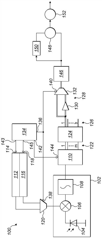
[0048] refer to figure 1 , the indirect time-of-flight distance calculation device 100 includes an electromagnetic radiation source (not shown), such as a laser diode (LD) or a light emitting diode (LED). In this example, the source of electromagnetic radiation is infrared light amplitude modulated for emission as a continuous wave optical signal according to an indirect time-of-flight measurement technique. The detection and ranging module of the apparatus includes an optical receiver photon mixer pixel device 102 that includes a photodiode 104 having an anode operatively coupled to ground potential and a coupling A cathode to a first input of a photon mixer 106 whose output is coupled to an input of an integrator 108 . The output of the integrator 108 is coupled to the input of a phase buffer 110 . In this example, a single photon mixer pixel device 102 is being described for simplicity and clarity of description. However, those skilled in the art will appreciate that the...


PUM


Abstract

An indirect time of flight range calculation apparatus (100) comprises a light source, a photonic mixer cell (102) that generates a plurality of output signals respectively corresponding to a first plurality of predetermined phase values (p1, p2, . . . , pm). A signal processing circuit (110, 124, 128, 146) is also provided to process the first plurality of electrical output signals in order to calculate a first vector and a first angle from the first vector. The photonic mixer (102) generates a second plurality of electrical output signals corresponding to a second plurality of predetermined phase values ([p1, p2, . . . , pm]+Pi / m). Each phase value of the second plurality of predetermined phase values is respectively offset with respect to each phase value of the first plurality of predetermined phase values by a predetermined phase offset value. The signal processing circuit (110, 124, 128, 146) processes the second plurality of electrical output signals in order to calculate a second vector, and de-rotates the second vector calculated and calculate a second angle from the de-rotated second vector before offsetting the second angle against the first angle, thereby generating a corrected output angle, which is used to calculate a range.

Description

technical field [0001] The present invention relates to an indirect time-of-flight distance calculation device of the type that uses phase delays to index measurements, for example. The invention also relates to a method of calculating the phase angle according to the indirect time-of-flight technique, of the type, for example, using a phase delay to index the measurement. Background technique [0002] In so-called time-of-flight sensing systems and other systems (such as game console vision systems), it is known to employ an illumination source to illuminate the surrounding environment (sometimes referred to as a "scene") within the illumination source's field of view, and to process Light reflected by features of this scene. Such so-called LiDAR (Light Detection and Ranging) systems use an illumination source to illuminate a scene with light, and a detection device (such as a photodiode array, some optical elements and a processing unit) to detect the light reflected from...

Claims


Application Information

Patent Timeline
IPC IPC(8): G01S17/32G01S7/4915
CPCG01S17/32G01S7/4915G01S17/36G01S17/89G01S17/46
Inventor A·奥特
Owner MELEXIS TECH NV
Learn More