
Rotary machine fault diagnosis method and system and storage medium

A technology for rotating machinery and fault diagnosis, which is applied in computer components, testing of machine/structural components, instruments, etc. It can solve problems such as difficult to apply to complex working conditions and low calculation efficiency, and achieve the effect of easy implementation and high calculation efficiency

Active Publication Date: 2021-04-09
HUAZHONG UNIV OF SCI & TECH
View PDF9 Cites 6 Cited by
  • Summary
  • Abstract
  • Description
  • Claims
  • Application Information

AI Technical Summary

Problems solved by technology

[0004] In view of the above defects or improvement needs of the prior art, the present invention provides a rotating machinery fault diagnosis method, system and storage medium, the purpose of which is to solve the technical problems of low calculation efficiency and difficulty in applying complex working conditions in the prior art

Method used


Image

  • Rotary machine fault diagnosis method and system and storage medium
  • Rotary machine fault diagnosis method and system and storage medium
  • Rotary machine fault diagnosis method and system and storage medium

Examples


Embodiment 1

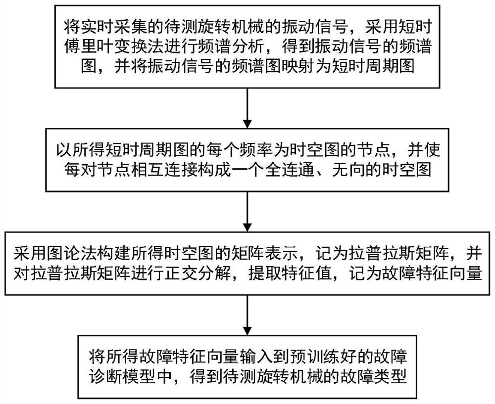
[0040] A fault diagnosis method for rotating machinery, such as figure 1 shown, including the following steps:

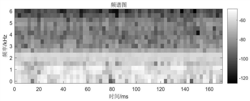
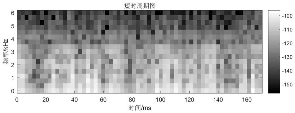
[0041] S1. Perform frequency spectrum analysis on the vibration signal of the rotating machine to be measured collected in real time by using the short-time Fourier transform method to obtain a frequency spectrum diagram of the vibration signal, and map the frequency spectrum diagram of the vibration signal into a short-time period diagram;

[0042] Specifically, the vibration signal {x(n)} of the rotating machine to be tested is collected by the accelerometer, and the frequency spectrum of the vibration signal of n∈[0,N-1] is expressed as:

[0043]

[0044] Among them, Y(k,m) is the spectrum amplitude when the frequency is kΔf and the time is mΔM; k is the frequency index, m is the time index; x(n) is the vibration signal at the nth sampling moment, and N is the vibration signal The length of , ΔM is the time interval, Δf is the frequency interval or weighting fu...

Embodiment 2

[0077] A rotating machinery fault diagnosis system, comprising:

[0078] The signal decomposition unit is used to analyze the vibration signal of the rotating machine to be measured in real time by using the short-time Fourier transform method to obtain the frequency spectrum of the vibration signal, and map the frequency spectrum of the vibration signal into a short-time period diagram ;

[0079] The eigenvector calculation unit uses each frequency of the obtained short-term period graph as a node of the space-time graph, and connects each pair of nodes to form a fully connected, undirected space-time graph; uses the graph theory method to construct the matrix representation of the obtained spatio-temporal graph , which is recorded as Laplacian matrix, and the Laplacian matrix is ​​decomposed orthogonally to extract eigenvalues, which are recorded as fault eigenvectors;

[0080] The fault diagnosis unit inputs the obtained fault feature vector into the pre-trained fault diag...

Embodiment 3

[0084] A computer-readable storage medium. A computer program is stored on the computer-readable storage medium. When the computer program is executed by a processor, the rotating machinery fault diagnosis method as described in Embodiment 1 is realized.

[0085] The relevant technical solutions are the same as those in Embodiment 1, and will not be repeated here.


PUM


Abstract

The invention discloses a rotary machine fault diagnosis method and system and a storage medium, and the method comprises the steps: S1, carrying out the spectral analysis of a vibration signal, collected in real time, of a to-be-detected rotary machine through employing a short-time Fourier transform method, obtaining a spectrogram of the vibration signal, and mapping the spectrogram of the vibration signal into a short-time periodic diagram; s2, taking each frequency of the obtained short-time periodic diagram as a node of a space-time diagram, and enabling each pair of nodes to be connected with each other to form a fully-connected and undirected space-time diagram; s3, adopting a graph theory method to construct matrix representation of the obtained space-time graph, recording the matrix representation as a Laplace matrix, carrying out orthogonal decomposition on the Laplace matrix, and extracting feature values, and recording the feature values as fault feature vectors; and S4, inputting the obtained fault feature vector into a pre-trained fault diagnosis model to obtain the fault type of the to-be-tested rotating machine. According to the method and system, the space-time diagram is combined with the Laplace matrix to extract the fault features, the calculation efficiency and the classification accuracy are greatly improved, and the method and system are suitable for fault diagnosis under complex working conditions.

Description

technical field [0001] The invention belongs to the technical field of fault diagnosis of rotating machinery, and more specifically relates to a method, system and storage medium for fault diagnosis of rotating machinery. Background technique [0002] Rotating machinery, as a key component of the machine transmission link, is widely used in modern manufacturing and industrial processes. In most practical applications, rotating machinery works in harsh or complex environments, such as high temperature, high pressure environment, variable speed and variable load. Rotating machinery may suffer from various damages and failures after long-term operation. These failures will affect system performance and seriously damage the machine. [0003] Fault diagnosis methods for rotating machinery include methods based on knowledge and experience feature calculation and feature self-learning. Among them, the method of feature calculation based on knowledge and experience first selects a...

Claims


Application Information

Patent Timeline
IPC IPC(8): G06K9/00G06K9/62G01M99/00
CPCG01M99/00G06F2218/08G06F2218/12G06F18/24147G06F18/29
Inventor 刘颉杨超颖周凯波张凯锋李尚元曹贯男张昌河
Owner HUAZHONG UNIV OF SCI & TECH
Learn More