Tandem wing layout solar unmanned aerial vehicle

A solar unmanned aerial vehicle and tandem wing technology, applied in the field of unmanned aerial vehicles, can solve the problems of small wing area, small effective lift surface, limited paving space for solar panels, etc., and achieve a simplified overall structure and easy installation. Effect

Active Publication Date: 2021-04-13
CHINA ACAD OF AEROSPACE AERODYNAMICS
View PDF20 Cites 1 Cited by
  • Summary
  • Abstract
  • Description
  • Claims
  • Application Information

AI Technical Summary

Problems solved by technology

[0003] Most of the existing conventional layout and flying wing layout solar drones have only one wing, which has the following disadvantages: (1) The effective lifting surface is small, and the drone's High wing load; (2) The wing area is small, and the space for installing solar panels is limited; (3) The wings are mostly slender structures with large aspect ratios, with large bending and torsional deformations, and large deformations affect the aerodynamic characteristics of the whole machine and The stability characteristics are adversely affected; (4) The flight speed is high and the flight power consumption is large

Method used


Image

  • Tandem wing layout solar unmanned aerial vehicle
  • Tandem wing layout solar unmanned aerial vehicle
  • Tandem wing layout solar unmanned aerial vehicle

Examples


Embodiment

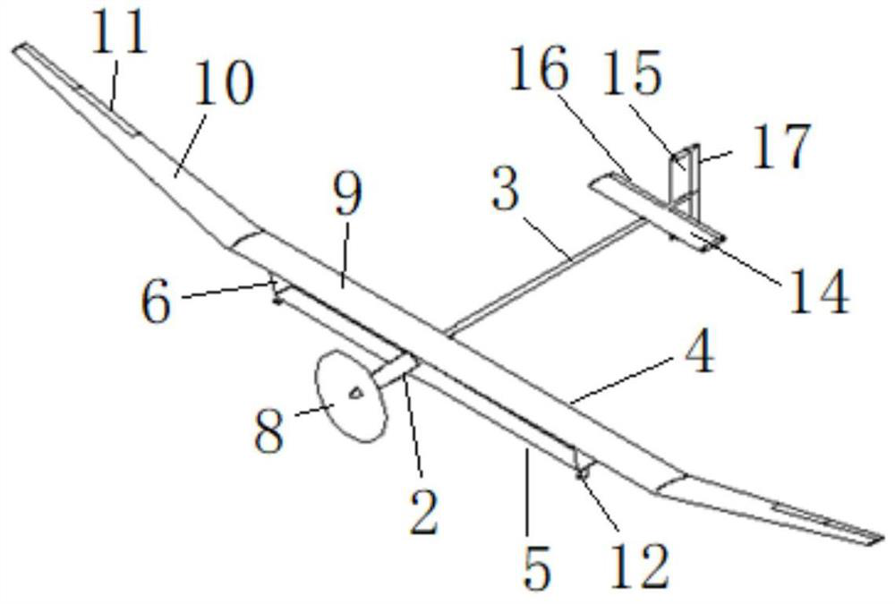
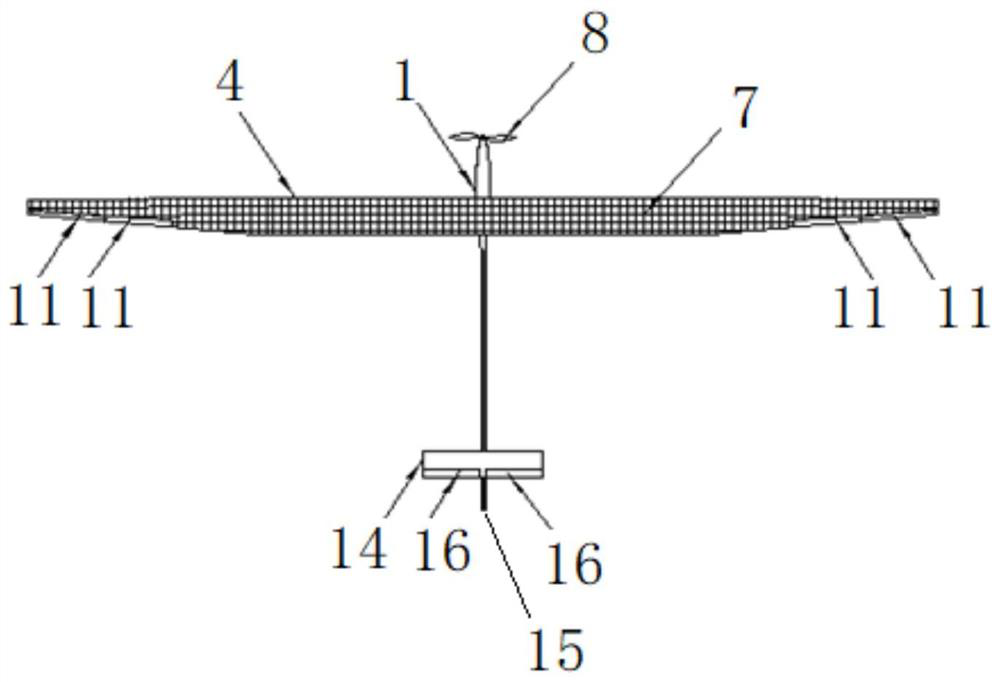
[0062] Such as Figure 1 to Figure 4 As shown, the present invention provides a kind of tandem wing layout solar drone, comprising:

[0063] Fuselage 1, the front end of the fuselage 1 is the cabin 2, and the rear end of the fuselage 1 is the fuselage bar 3;

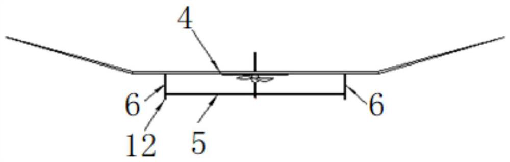
[0064] The upper wing 4 and the lower wing 5 are arranged on the upper side and the lower side of the nacelle 2 respectively, and the upper wing 4 and the lower wing 5 are connected by side plates 6 arranged on both sides of the nacelle 2 to form a frame structure;

[0065] The solar panel 7 is laid on the upper surface of the upper wing 4 and the lower wing 5;

[0066] The empennage is arranged on the tail of the fuselage bar 3;

[0067] The propeller 8 is arranged at the front end of the nacelle 2;

[0068] The landing gear is arranged on the lower side of the tandem wing layout solar unmanned aerial vehicle.

[0069] In this embodiment, the nacelle 2 is in the shape of an ellipsoid. The nacelle 2 is equipped with ...


PUM


Abstract

The invention discloses a tandem wing layout solar unmanned aerial vehicle, which relates to the technical field of unmanned aerial vehicles and comprises a fuselage, a cabin is arranged at the front end of the fuselage, and a fuselage rod is arranged at the rear end of the fuselage; an upper wing and a lower wing which are arranged on the upper side and the lower side of the cabin respectively, and the upper wing and the lower wing are connected through side plates arranged on the two sides of the cabin to form a frame type structure; solar cell panels which are laid on the upper surfaces of the upper wing and the lower wing; an empennage which is arranged at the tail part of the fuselage rod; a propeller which is arranged at the front end of the cabin; and an undercarriage which is arranged on the lower side of the tandem wing layout solar unmanned aerial vehicle; the tandem wing layout solar unmanned aerial vehicle is provided with the upper wing and the lower wing, the effective wing area is increased, and the wing load is low; the wing area is increased, and the laying area of the solar cell panel is enlarged; the upper wing and the lower wing are connected through the side plates to form a frame structure, the structural rigidity is improved, and wing deformation is reduced; the flight speed and the flight power consumption are reduced.

Description

technical field [0001] The invention belongs to the technical field of unmanned aerial vehicles, and more specifically relates to a solar unmanned aerial vehicle with a tandem wing layout. Background technique [0002] Solar-powered drones are electric unmanned aerial vehicles that rely on solar radiation as their energy source. During the day, they rely on solar cells to maintain normal flight. The excess solar energy is stored as battery power and converted into high potential energy. At night, it uses battery power and glides to continue flying. At present, the main shortcoming of solar drones lies in the low energy density of the energy system. Therefore, it is necessary to "maximize production capacity" and "less energy consumption" as much as possible to improve the performance of drones. The technical way to achieve "multiple production capacity" is to use high-efficiency solar panels and install more solar panels to increase energy acquisition, and the technical way ...

Claims


Application Information

Patent Timeline
Patent Type & Authority Applications(China)
IPC IPC(8): B64C3/00B64C39/02
CPCB64C3/00B64C39/02B64D2211/00B64U10/25B64U30/10B64U50/19B64U2101/00
Inventor 张凯仲维国佟阳李喜乐李广佳
Owner CHINA ACAD OF AEROSPACE AERODYNAMICS
Why Eureka
Try Eureka