Empty frame and full frame switching mechanism for automobile accessory stacking machining

A technology for auto parts and switching mechanisms, which is applied in the stacking of objects, conveyors, conveyor objects, etc., can solve the problems of inconvenient use, inconvenience to be parallel to each other, and the auxiliary mechanism occupies a large space, and achieves high adaptability, Small footprint and the effect of ensuring mobile stability

Active Publication Date: 2021-04-13
UNIPRES GUANGZHOU
View PDF6 Cites 0 Cited by
  • Summary
  • Abstract
  • Description
  • Claims
  • Application Information

AI Technical Summary

Problems solved by technology

[0004] The purpose of the present invention is to provide an empty frame full frame switching mechanism for auto parts stacking processing, which solves the problem that most of the auxiliary stacking mechanical equipment on the market is arranged in a straight line during use, and it is difficult to realize the empty frame and full frame of the parts. The effect of turning and switching the full frame is not convenient to keep the feeding direction of the empty frame and the discharging direction of the full frame parallel to each other, and the existing auxiliary mechanism takes up a lot of space, which is very inconvenient to use

Method used


Image

  • Empty frame and full frame switching mechanism for automobile accessory stacking machining
  • Empty frame and full frame switching mechanism for automobile accessory stacking machining
  • Empty frame and full frame switching mechanism for automobile accessory stacking machining

Examples


Embodiment Construction

[0026] The following will clearly and completely describe the technical solutions in the embodiments of the present invention with reference to the accompanying drawings in the embodiments of the present invention. Obviously, the described embodiments are only some, not all, embodiments of the present invention. Based on the embodiments of the present invention, all other embodiments obtained by persons of ordinary skill in the art without making creative efforts belong to the protection scope of the present invention.

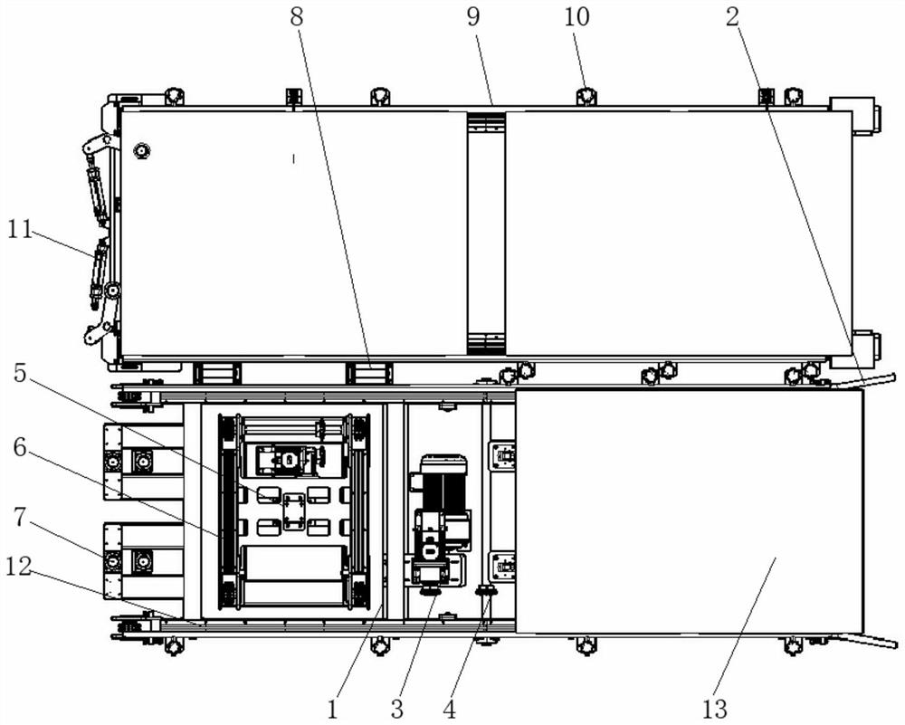
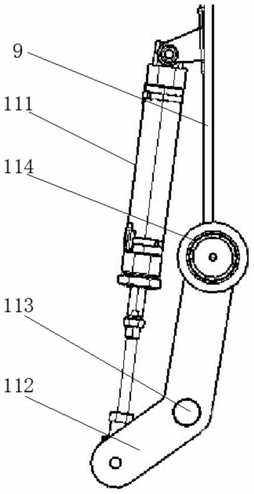
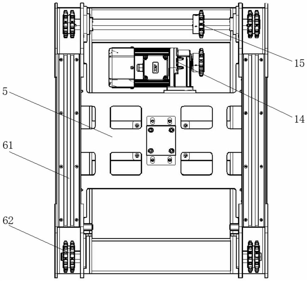
[0027] see Figure 1-5 , an empty frame full frame switching mechanism for auto parts stacking processing, comprising an empty frame moving frame 1, a guide plate 2, a first motor 3, a first driving rod 4, a lifting mechanism 5, a Y-axis moving assembly 6, and a chain support Frame 61, sprocket 62, rotation auxiliary assembly 7, pressure column 71, pressure sensor 72, rotary motor 73, controller 74, transition assembly 8, rotating roller 81, bracket 82, full f...


PUM


Abstract

The invention discloses an empty frame and full frame switching mechanism for automobile accessory stacking machining. The empty frame and full frame switching mechanism comprises an empty frame moving frame, a full frame moving frame and a telescopic auxiliary assembly; guide plates are installed on the right side of the empty frame moving frame; a first motor is arranged in the middle of the interior of the empty frame moving frame; a first driving rod is installed on the right side of the first motor; a lifting mechanism is arranged on the left side of the first motor; Y-axis moving assemblies are arranged on the left side and the right side of the upper surface of the lifting mechanism correspondingly; the full frame moving frame is installed on the rear side of transition assemblies; positioning rods are arranged on the outer edge and the inner edges of the full frame moving frame and the outer edge and the inner edge of the empty frame moving frame correspondingly; the telescopic auxiliary assembly is installed at the left end of the full frame moving frame; and X-axis moving assemblies are installed on the front side and the rear side of the upper surface of the full frame moving frame and the front side and the rear side of the upper surface of the empty frame moving frame correspondingly. According to the empty frame and full frame switching mechanism for automobile accessory stacking machining, the feeding direction of empty frames and the discharging direction of full frames are kept parallel to each other, the overall occupied space is small, and the mechanism is suitable for being used in various different production and machining environments and higher in adaptability.

Description

technical field [0001] The invention relates to the technical field of auto parts processing, in particular to an empty frame full frame switching mechanism for stacking and processing auto parts. Background technique [0002] Auto parts are the various units that make up the whole car and a product that serves the car. With the increasingly fierce competition in the auto parts processing market, the popularization of the concept of environmental protection, and the continuous upgrading and application of technology, the international auto parts processing parts industry In recent years, the following development characteristics have emerged: ①The trend of auto parts processing system matching and modular supply is in the ascendant; ②The globalization of auto parts processing and procurement; ③The transfer speed of the auto parts processing industry is accelerating. Auto parts need to use a lot of mechanical equipment to assist in the processing process, so as to save more l...

Claims


Application Information

Patent Timeline
IPC IPC(8): B65G13/00B65G13/11B65G23/06B65G17/40B65G47/82B65G57/03B65G43/08
CPCB65G13/00B65G13/11B65G23/06B65G17/40B65G47/82B65G57/03B65G43/08B65G2201/0235B65G2203/042
Inventor 吴艳东
Owner UNIPRES GUANGZHOU
Why Eureka
Try Eureka