Moving bed type blast furnace gas desulfurization device and desulfurization method thereof
A blast furnace gas and desulfurization device technology, applied in the field of desulfurization, can solve problems such as imperfect blast furnace gas desulfurization device, and achieve the effects of improving blast furnace gas desulfurization efficiency, large mass transfer area, and high purification efficiency
- Summary
- Abstract
- Description
- Claims
- Application Information
AI Technical Summary
Problems solved by technology
Method used
Image

Examples
Embodiment 1
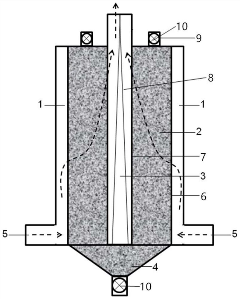
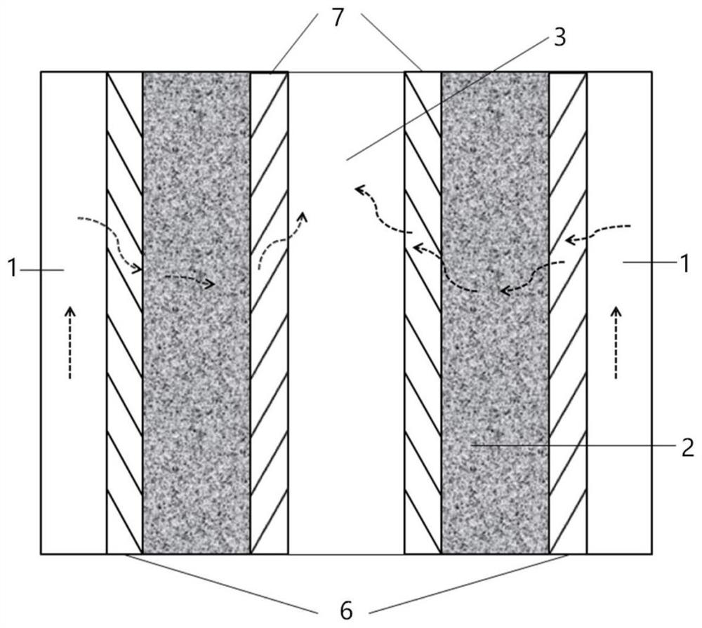
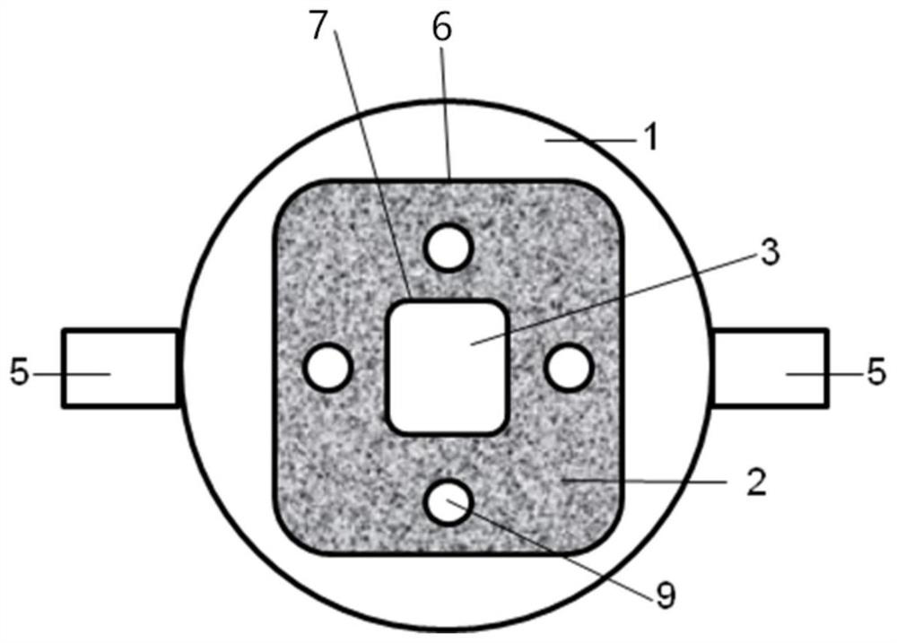
[0057] The present invention provides a moving bed type blast furnace gas desulfurization device. The blast furnace gas desulfurization device is such as figure 1 As shown, it includes a casing, and a catalyst separator group is arranged axially inside the casing. The catalyst separator group includes an inner ring separator member 7 and an outer ring separator member 6 that are coaxially nested from the inside to the outside. The spherical iron oxide catalyst 2 is filled in the annular cavity formed between the inner ring partition member 7 and the outer ring partition member 6, and the top of the shell where the annular cavity is located is provided with a feed port 9, and the catalyst 2 is formed from the top of the shell. The feed port 9 is injected and discharged from the bottom of the shell along the annular cavity. The cavity enclosed by the inner ring partition member 7 is the exhaust channel 3 , the cavity between the outer ring partition member 6 and the shell is the...
Embodiment 2
[0063] The present invention provides a moving bed type blast furnace gas desulfurization device. The blast furnace gas desulfurization device is such as figure 1 As shown, it includes a casing, and a catalyst separator group is arranged axially inside the casing. The catalyst separator group includes an inner ring separator member 7 and an outer ring separator member 6 that are coaxially nested from the inside to the outside. A cylindrical zinc oxide catalyst 2 is filled in the annular cavity formed between the inner ring partition member 7 and the outer ring partition member 6. The top of the shell where the annular cavity is located is provided with a feed port 9, and the catalyst 2 is formed by the shell. The top feed port 9 is injected and discharged from the bottom of the shell along the annular cavity. The cavity enclosed by the inner ring partition member 7 is the exhaust channel 3 , the cavity between the outer ring partition member 6 and the shell is the intake chann...
Embodiment 3
[0069] This embodiment provides a moving bed type blast furnace gas desulfurization device. The blast furnace gas desulfurization device is such as figure 1 As shown, it includes a casing, and a catalyst separator group is arranged axially inside the casing. The catalyst separator group includes an inner ring separator member 7 and an outer ring separator member 6 that are coaxially nested from the inside to the outside. The annular cavity formed between the inner ring partition member 7 and the outer ring partition member 6 is filled with a cube-shaped activated carbon catalyst 2. The top of the shell where the annular cavity is located is provided with a feed port 9, and the catalyst 2 is formed from the top of the shell. The feed port 9 is injected and discharged from the bottom of the shell along the annular cavity. The cavity enclosed by the inner ring partition member 7 is the exhaust channel 3 , the cavity between the outer ring partition member 6 and the shell is the i...
PUM
| Property | Measurement | Unit |
|---|---|---|
| angle | aaaaa | aaaaa |
| angle | aaaaa | aaaaa |
Abstract
Description
Claims
Application Information
 - R&D
- Intellectual Property
- Life Sciences
- Materials
- Tech Scout
- Unparalleled Data Quality
- Higher Quality Content
- 60% Fewer Hallucinations
Browse by: Latest US Patents, China's latest patents, Technical Efficacy Thesaurus, Application Domain, Technology Topic, Popular Technical Reports.
© 2025 PatSnap. All rights reserved.Legal|Privacy policy|Modern Slavery Act Transparency Statement|Sitemap|About US| Contact US: help@patsnap.com