Non-azeotropic-mixed-refrigerant-based diesel exhaust heat recovery system with combined power-cold supply and compound cycle
A waste heat recovery system, non-azeotropic mixing technology, applied to internal combustion piston engines, combustion engines, machines using waste heat, etc., can solve problems such as difficulty in improving the fuel utilization rate of internal combustion engines, and achieve high compactness, convenient operation adjustment, and enhancement. The effect of the cooling effect
- Summary
- Abstract
- Description
- Claims
- Application Information
AI Technical Summary
Problems solved by technology
Method used
Image

Examples
Embodiment 1
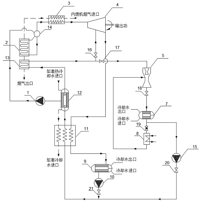
[0033] Such as figure 1 and 5 As shown, the internal combustion engine waste heat recovery system based on the non-azeotropic mixed working fluid combined power and cooling cycle includes ORC liquid supply pump 1, ORC steam generator 2, ORC superheater 3, ORC turbine 4, injector 5, Condenser 7, refrigeration evaporator 8, condenser 9, low-pressure liquid supply pump 10, low-pressure preheater 11, steam generator 12, low-pressure superheater 13, steam drum 14, mixer 15, regulating valve, stop valve and throttle valve;
[0034] The high-temperature flue gas of the internal combustion engine passes through the ORC superheater 3, the ORC steam generator 2, and the low-pressure superheater 13 successively, and then discharges heat;
[0035] The hot cooling water of the cylinder liner is discharged through the heat exchange of the steam generator 12 and the heat release of the low-pressure preheater 11 in sequence;
[0036] The liquid mixed working medium in the condenser 9 is se...
Embodiment 2
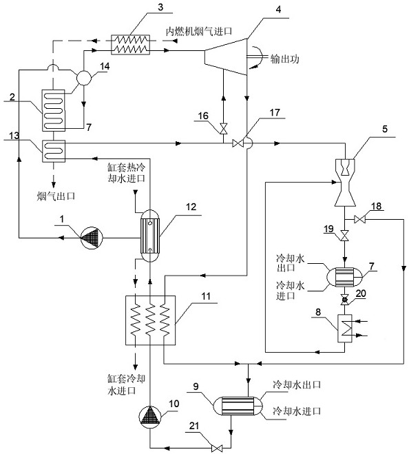
[0039] Such as figure 2 and 5 As shown, the internal combustion engine waste heat recovery system based on the non-azeotropic mixed working fluid combined power and cooling cycle includes ORC liquid supply pump 1, ORC steam generator 2, ORC superheater 3, ORC turbine 4, injector 5, Condenser 7, refrigeration evaporator 8, condenser 9, low-pressure liquid supply pump 10, low-pressure preheater 11, steam generator 12, low-pressure superheater 13, steam drum 14, mixer 15, regulating valve, stop valve and throttle valve;
[0040] The high-temperature flue gas of the internal combustion engine passes through the ORC superheater 3, the ORC steam generator 2, and the low-pressure superheater 13 successively, and then discharges heat;
[0041] The hot cooling water of the cylinder liner is discharged through the heat exchange of the steam generator 12 and the heat release of the low-pressure preheater 11 in sequence;
[0042] The liquid mixed working medium in the condenser 9 is d...
Embodiment 3
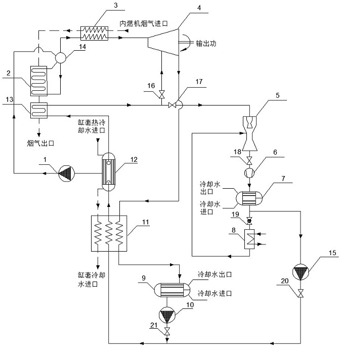
[0045] Such as image 3 and 5 As shown, the internal combustion engine waste heat recovery system based on the non-azeotropic mixed working fluid combined power and cooling cycle includes ORC liquid supply pump 1, ORC steam generator 2, ORC superheater 3, ORC turbine 4, injector 5, Compressor 6, condenser 7, refrigeration evaporator 8, condenser 9, low pressure liquid supply pump 10, low pressure preheater 11, steam generator 12, low pressure superheater 13, steam drum 14, mixer 15, regulating valve , cut-off valve and throttle valve;
[0046] The high-temperature flue gas of the internal combustion engine passes through the ORC superheater 3, the ORC steam generator 2, and the low-pressure superheater 13 successively, and then discharges heat;
[0047] The hot cooling water of the cylinder liner is discharged through the heat exchange of the steam generator 12 and the heat release of the low-pressure preheater 11 in sequence;
[0048] The liquid mixed working medium in the...
PUM
 Abstract
Description
Claims
Application Information
 - Generate Ideas
- Intellectual Property
- Life Sciences
- Materials
- Tech Scout
- Unparalleled Data Quality
- Higher Quality Content
- 60% Fewer Hallucinations
Browse by: Latest US Patents, China's latest patents, Technical Efficacy Thesaurus, Application Domain, Technology Topic, Popular Technical Reports.
© 2025 PatSnap. All rights reserved.Legal|Privacy policy|Modern Slavery Act Transparency Statement|Sitemap|About US| Contact US: help@patsnap.com