Transformer production process

A production process and transformer technology, applied in the direction of inductance/transformer/magnet manufacturing, electrical components, circuits, etc., can solve the problems of increasing the labor intensity of operators, and achieve the effect of easy maintenance and lightening rigid contact

Active Publication Date: 2021-04-13
无锡市凯达电讯电器有限公司
View PDF6 Cites 2 Cited by
  • Summary
  • Abstract
  • Description
  • Claims
  • Application Information

AI Technical Summary

Problems solved by technology

[0005] The existing coil includes a coil frame and copper wires wound on the coil frame. However, after the above-mentioned winding machine is finished winding, the copper wire is generally cut off manually, which will increase the labor intensity of the operator.

Method used


Image

  • Transformer production process
  • Transformer production process
  • Transformer production process

Examples


Embodiment

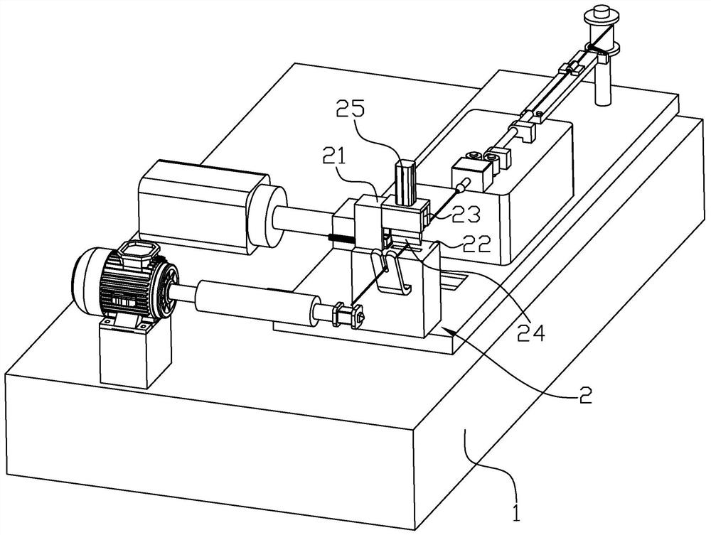
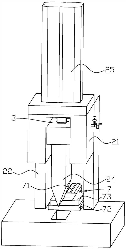
[0038] Embodiment: a kind of transformer production technique, as figure 1 and figure 2 As shown, including: S1, preparation process; S2, winding Ⅰ; S3, winding Ⅱ; S4, glue wrapping; S5, shaping glue wrapping; S6, wire cutting and stripping paint; S7, iron core assembly; High voltage; S9, bundled steel strip, measuring inductance high voltage; S10, appearance inspection, vacuum impregnation; S11, wire trimming, paint stripping, tinning; S12, lead wire twisting; S13, lead wire welding, encapsulation; S14, broken wire, Heat-shrinkable sleeve, wire binding; S15, QC electrical test; S16, paste model logo; S17, appearance inspection; S18, packaging; step S2: first press the reset button of the winding machine, and then make the copper wire pass through the winding machine in turn wire wheel, wire breaking device 2 and winding device; next, the copper wire is wound on the bobbin by the winding device, and when the copper wire on the bobbin is wound to completion, the copper wire i...


PUM


Abstract

The invention discloses a transformer production process, and relates to the technical field of machine tool transformers. The transformer production process comprises the following steps: S2, firstly, pressing a reset key of a winding machine, and then enabling a copper wire to sequentially pass through a wire guide wheel, a wire breaking device and a winding device of the winding machine; and then winding the copper wire on a coil rack through the winding device, and after the copper wire on the coil rack is wound, cutting off the copper wire through the wire breaking device. The winding machine comprises a machine table. The wire breaking device comprises a wire breaking frame fixedly connected to the top of the machine table, a wire cutting opening formed in one side of the wire breaking frame and a vertical groove formed in the top of the wire breaking frame and communicated with the wire cutting opening. A cutter is slidably connected into the vertical groove in the vertical direction, a wire breaking air cylinder is installed at the top of the wire breaking frame, and a piston rod of the wire breaking air cylinder is detachably connected to the top of the cutter. According to the winding machine, the wire breaking device is additionally arranged on the winding machine, copper wires can be conveniently cut off, and therefore the labor intensity of operators can be reduced.

Description

technical field [0001] The invention relates to the technical field of machine tool transformers, more specifically, it relates to a transformer production process. Background technique [0002] The development of machine tool control transformers in our country has experienced more than 10 years of development, and now the technology is relatively mature. The following is an introduction to the development of JBK5 series machine tool control transformers as an example. JBK5 series machine tool control transformers are the latest Satons transformer series imported from Germany in the mid-1990s. Based on the domestic JBK3 series machine tool control transformers, after years of further absorption of similar foreign products, the terminal structure of foreign advanced methods is optimized, and the terminals are connected to the transformer. The frames are combined to increase the degree of protection to IP2LX, preventing accidental contact with the circuit. Using domestic IT ...

Claims


Application Information

Patent Timeline
Patent Type & Authority Applications(China)
IPC IPC(8): H01F41/00H01F41/076
CPCH01F41/00H01F41/076
Inventor 陆方明周一新曹敏霞
Owner 无锡市凯达电讯电器有限公司
Why Eureka
Try Eureka