
Trench gate type IGBT structure

A trench gate, trench gate technology, applied in semiconductor devices, electrical components, circuits, etc., can solve the problems of trench gate IGBT voltage drop, large transmission capacitance, and large device loss

Pending Publication Date: 2021-04-13
GLOBAL ENERGY INTERCONNECTION RES INST CO LTD +2
View PDF0 Cites 0 Cited by
  • Summary
  • Abstract
  • Description
  • Claims
  • Application Information

AI Technical Summary

Problems solved by technology

[0010] In order to solve the problems of trench gate IGBT voltage drop, large transmission capacitance, and large device loss in the prior art, the present invention provides a trench gate IGBT structure, which can reduce the PNP component, enhance the conductance modulation effect, and reduce the cost of the chip. saturation voltage drop, reducing the transfer capacitance

Method used


Image

  • Trench gate type IGBT structure
  • Trench gate type IGBT structure
  • Trench gate type IGBT structure

Examples


Embodiment Construction

[0036] In order to better understand the present invention, the content of the present invention will be further described below in conjunction with the accompanying drawings and examples.

[0037] In order to overcome the structural defects of existing chips, the invention provides a trench gate IGBT structure.

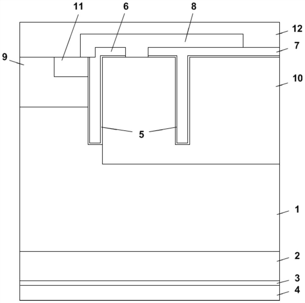
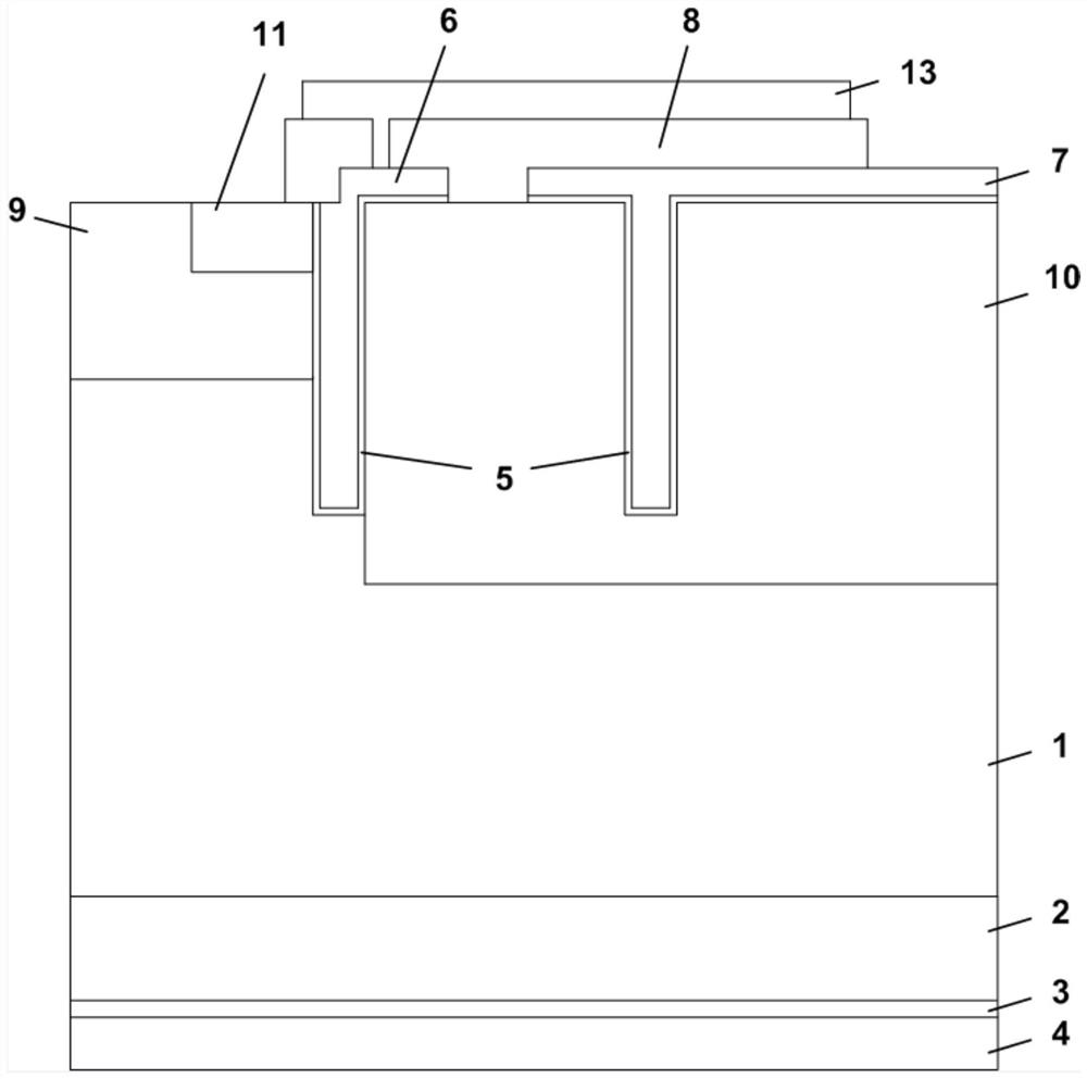
[0038] Such as figure 1 and figure 2 As shown, compared with the ordinary trench gate IGBT chip, this structure separates the gate polycrystalline etching isolation outside the trench to form two parts, the polysilicon trench gate structure 6 and the polysilicon dummy gate structure 7, in which the polysilicon The polysilicon in the trench of the dummy gate structure 7 is not connected to the external electrode to form a dummy gate, and at the same time, the isolation oxide layer 8 is isolated from oxygen and etched to form a contact hole, and the polysilicon dummy gate structure 7 is connected to the N-type dummy gate structure 7 through the front metal electrode ...


PUM


Abstract

The invention provides a trench gate type IGBT structure. The IGBT structure comprises an N-type doped emitter region (11), a P-type doped deep junction region (10) and a polycrystalline silicon dummy gate structure (7); and the polycrystalline silicon dummy gate structure (7) is connected with the N-type doped emitter region (11), and the bottom of the polycrystalline silicon dummy gate structure (7) is inserted into the P-type doped deep junction region (10). By adding the polycrystalline silicon dummy gate structure (7), reducing PNP component, enhancing conductivity modulation effect and reducing saturation voltage drop of the chip, the polycrystalline silicon dummy gate structure (7) is close to the back metal electrode (4) and connected with the N-type doped emitter region (11), transmission capacitance of a cellular region of the trench gate type IGBT chip can be effectively reduced, dynamic loss of the IGBT chip is reduced, and the overall performance is enhanced.

Description

technical field [0001] The invention relates to the technical field of semiconductors, in particular to a trench gate type IGBT structure. Background technique [0002] The IGBT can be divided into two regions: one is the bipolar pnp region and the other is the pin region. In the transistor region, the IGBT behaves like a pnp transistor in saturation mode, with the collector terminal of the IGBT corresponding to the emitter terminal of the pnp transistor. In the pin area, the IGBT behaves like a pin diode. [0003] In the pnp transistor region, the carrier concentration is the highest at the J1 junction and decreases toward the J2 junction; it is almost reduced to zero at the J2 junction. The region under the gate has the same carrier distribution as the ideal pin diode, so it is called the pin region; the channel of the MOS transistor is an ideal emitter, which provides electron flow and forms an electron accumulation layer under the gate. Depend on figure 1 It can be s...

Claims


Application Information

Patent Timeline
IPC IPC(8): H01L29/739H01L29/423
CPCH01L29/4236H01L29/7397
Inventor 金锐李立和峰赵哿王耀华刘江高明超吴军民潘艳白鹭李冠良
Owner GLOBAL ENERGY INTERCONNECTION RES INST CO LTD
Learn More