
High-speed cap screwing device and cap screwing machine

A high-speed, capping technology, applied in the direction of screw caps, etc., can solve the problems of damaging caps or bottles, affecting the speed of capping, and not working properly, and achieves the effects of increasing speed, saving pipelines, and compact structure

Pending Publication Date: 2021-04-16
GUANGZHOU PHARMA INTELLIGENT EQUIP CO LTD
View PDF0 Cites 0 Cited by
  • Summary
  • Abstract
  • Description
  • Claims
  • Application Information

AI Technical Summary

Problems solved by technology

Existing capping machines are generally equipped with one or more capping components. If the number of capping components is too small, the capping speed will be affected. If the number is too large, they will affect each other, especially The rotation and rotation of the existing screw cap components are all driven by the same drive mechanism. If a synchronous belt is used to drive the rotation of each screw cap component synchronously, this driving method will inevitably cause mutual interference between the screw cap components. When one of the components fails When the problem occurs, the remaining components will be affected and cannot work normally, and it is difficult to trace which component has the problem and take targeted measures when there is an unqualified screw cap problem
In addition, most of the existing caps are made of plastic. If the strength of grasping and twisting the cap is not properly controlled, it will damage the cap or bottle, or the screw will not be tightened tightly, which will greatly reduce the yield.

Method used


Image

  • High-speed cap screwing device and cap screwing machine
  • High-speed cap screwing device and cap screwing machine
  • High-speed cap screwing device and cap screwing machine

Examples


Embodiment Construction

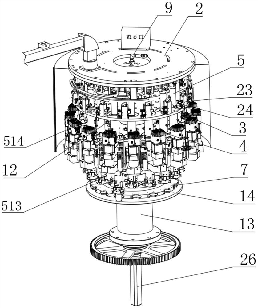
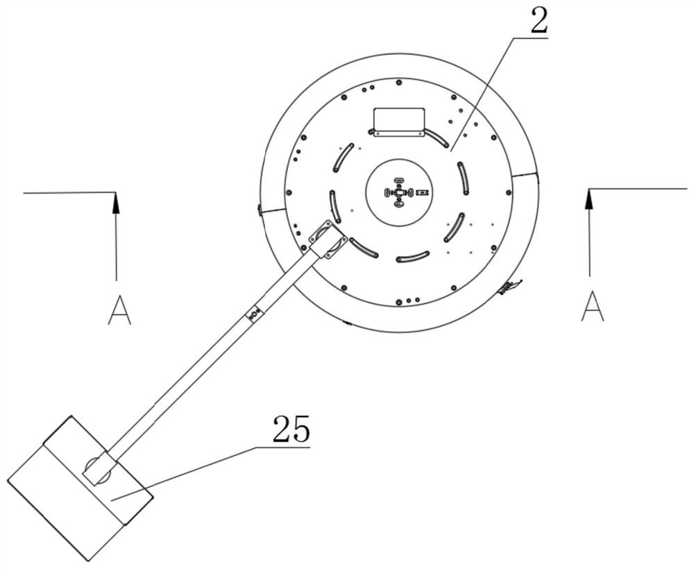
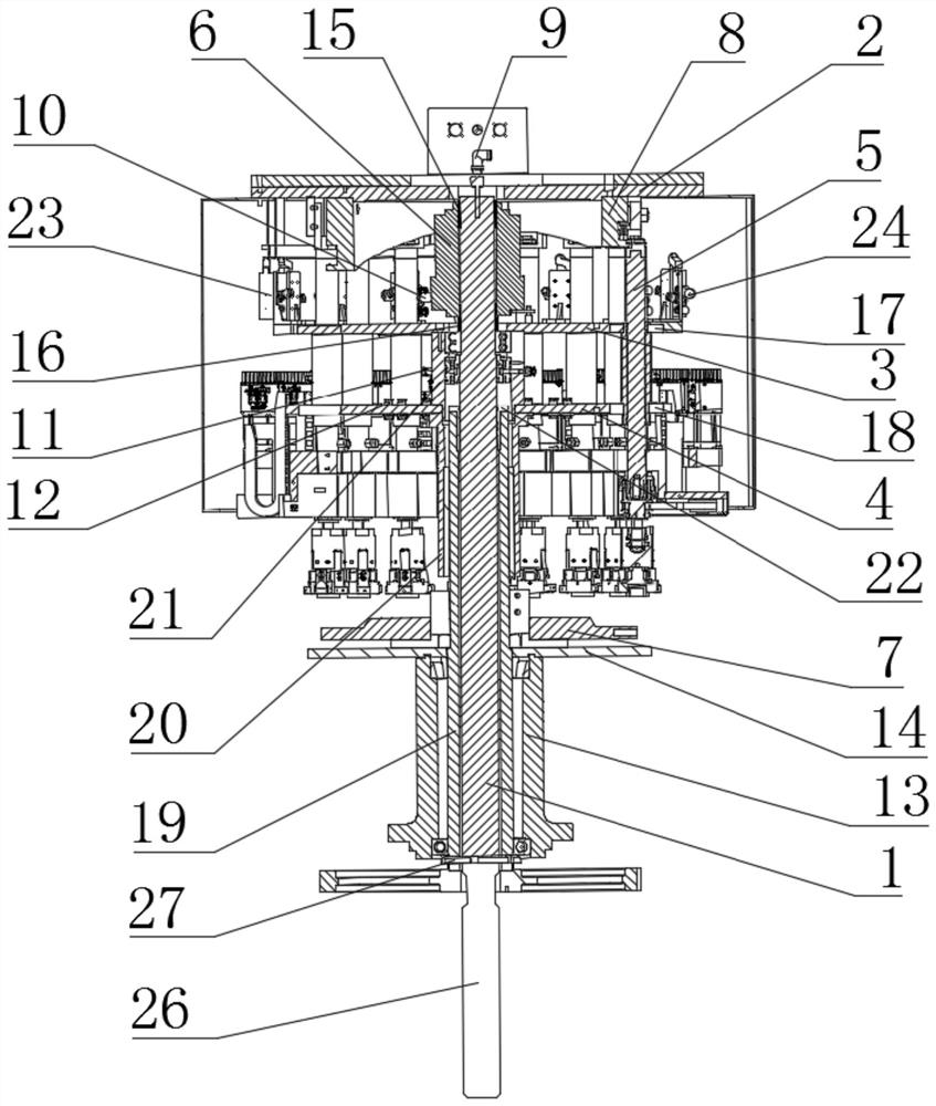
[0027] A high-speed capping device 1-1, such as Figure 1 to Figure 3As shown, it includes a main body panel 2 , a rotating shaft 1 , a rotating support frame, a main astrolabe 7 , a slip ring 6 and a screw cap assembly 5 , and a control panel 25 is also connected to the main body panel 2 . The main body panel 2 is fixed on the frame, the main body panel 2 is provided with a cover cam 8, the upper end of the rotating shaft 1 is rotatably connected with the main body panel 2, and the rotating shaft 1 is connected to the rotating shaft The support frames are fixedly connected to drive the rotating support frame to rotate. There are various forms and structures of the rotating support frame. As one of the implementations, the rotating support frame of this embodiment includes an upper rotating disk 3, a lower rotating disk 4 and a support assembly arranged at intervals along the rotating shaft 1. .

[0028] There are several screw cap assemblies 5, and several of the screw cap ...


PUM


Abstract

The invention discloses a high-speed cap screwing device and a cap screwing machine. The high-speed cap screwing device comprises a main body panel, a rotating shaft, a rotating and supporting frame, a main star disc, a sliding ring and cap screwing assemblies, the rotating shaft is fixedly connected with the rotating and supporting frame to drive the rotating and supporting frame to rotate, the plurality of cap screwing assemblies are distributed in an annular array with the rotating shaft as the axis, each cap screwing assembly is independently provided with a driving component, a circuit sequentially penetrates through a circuit inlet, the sliding ring and the rotating and supporting frame to be connected with an electric component on each cap screwing assembly, and working gas is connected with a pneumatic component on each cap screwing assembly through a gas path channel and the rotating and supporting frame. According to the high-speed cap screwing device and the cap screwing machine, the plurality of sets of cap screwing assemblies working at the same time are arranged, the cap screwing speed is increased, each cap screwing assembly is independently driven and independently operates, mutual influences are avoided, and independent control, maintenance and fault tracing are facilitated; all the screw cap assemblies are not wound with each other, and the structure is compact; and all the components can achieve stable transmission and good sealing, and products cannot be damaged during cap screwing.

Description

technical field [0001] The invention relates to the technical field of packaging machinery and equipment, in particular to a high-speed capping device and a capping machine using the high-speed capping device. Background technique [0002] All kinds of packaging bottles are mostly sealed and packaged by screwed caps, so capping machines are needed for packaging to improve the automation of the production line. Existing capping machines are generally equipped with one or more capping components. If the number of capping components is too small, the capping speed will be affected. If the number is too large, they will affect each other, especially The rotation and rotation of the existing screw cap components are all driven by the same drive mechanism. If a synchronous belt is used to drive the rotation of each screw cap component synchronously, this driving method will inevitably cause mutual interference between the screw cap components. When one of the components fails Whe...

Claims


Application Information

Patent Timeline
IPC IPC(8): B67B3/20
Inventor 姜德伟黎业演刘桂安饶清华周国健王耀炜
Owner GUANGZHOU PHARMA INTELLIGENT EQUIP CO LTD
Features
  • Generate Ideas
  • Intellectual Property
  • Life Sciences
  • Materials
  • Tech Scout
  • Unparalleled Data Quality
  • Higher Quality Content
  • 60% Fewer Hallucinations
Learn More