
Drilling machine power head assembly, drilling machine power drill bit, and spiral drilling and production machine

A drilling rig power head, drilling machine technology, applied in the field of drilling rig power drill bit, drilling rig power head assembly, auger drilling machine, can solve the problems of heavy weight, low work efficiency, constant speed of driving mechanism, etc., to achieve convenient movement and rotation field, low maintenance cost and low failure rate

Pending Publication Date: 2021-04-16
山东建隆工程机械有限公司
View PDF0 Cites 0 Cited by
  • Summary
  • Abstract
  • Description
  • Claims
  • Application Information

AI Technical Summary

Problems solved by technology

However, the mining of thin coal seams is extremely difficult, the work efficiency is very low, and the safety is poor. Problems have always restricted the production continuity and sustainable development of coal enterprises, resulting in the premature failure of some mining areas, which has led to the increasing task of tapping the potential and utilization of coal resources in our country.
[0005] 1. The drive mechanism in which the motor is directly connected to the mechanical gearbox is bulky and heavy (about 50 tons). When mining, a wide roadway needs to be excavated, which is not conducive to moving and transitioning in a narrow roadway, and excavation Wider roadways will increase the construction cost of coal mines;
[0006] 2. The drive mechanism in which the motor is directly connected to the mechanical gearbox, the drive motor has unsafe factors such as motor overload and stalling;
[0007] 3. The driving mechanism is a rigid mechanical connection. Due to the complex internal structure of the mechanical gearbox, the driving mechanism will produce a large impact when the load changes frequently, causing damage to the gearbox, and the maintenance cost of the gearbox is high;
[0008] 4. The speed of the driving mechanism is constant, and the speed cannot be adjusted in real time according to the demand

Method used


Image

  • Drilling machine power head assembly, drilling machine power drill bit, and spiral drilling and production machine
  • Drilling machine power head assembly, drilling machine power drill bit, and spiral drilling and production machine
  • Drilling machine power head assembly, drilling machine power drill bit, and spiral drilling and production machine

Examples


Embodiment 1

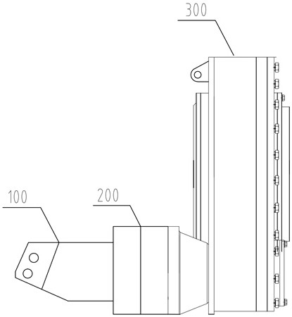
[0054] as attached figure 1 As shown, a drill power head assembly provided for an embodiment of the present invention includes:

[0055] Drill pipe drive reduction box 300, used to install the drill pipe 400 for drilling the coal seam;

[0056] Planetary reducer 200; the drill pipe driving reducer 300 is installed on the planetary reducer 200, and is connected with the planetary reducer 200 in transmission;

[0057] The variable hydraulic motor 100 is used to provide power to the planetary reducer 200 so that the drill rod 400 installed on the drill rod drive reducer 300 can achieve multi-speed or stepless speed change.

[0058] The working principle of the embodiment of the present invention is as follows:

[0059]The variable hydraulic motor 100 drives the planetary reducer 200 to run, and the planetary reducer 200 drives the drill rod drive reducer 300 to run. The power output end of the drill rod drive reducer 300 is used to install the drill rod 400 for drilling the coa...

Embodiment 2

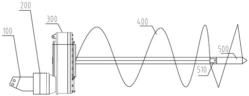
[0066] as attached figure 2 As shown, one embodiment of the present invention also provides a drill power drill bit, comprising:

[0067] drill bit 500;

[0068] Drill rod 400; the drill bit 500 is arranged at one end of the drill rod 400;

[0069] The drill head assembly in Embodiment 1; the drill rod 400 is installed on the drill rod driving reduction box 300 of the drill head assembly.

[0070] as attached figure 2 As shown, as a preferred embodiment of the present invention, the drill bit 500 and the drill rod 400 are both helical.

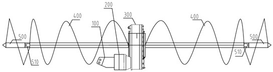
[0071] as attached image 3 As shown, as a preferred embodiment of the present invention, the drill bit 500 and the drill rod 400 are provided with two parts, and the drill rod drive reduction box 300 has two power output ends; the two drill bits 500 are respectively arranged on two One end of the drill rod 400, and the two drill rods 400 are respectively installed on the two power input and output ends of the drill rod drive reduction ...

Embodiment 3

[0076] as attached Figure 4 As shown, an embodiment of the present invention also provides a kind of auger drilling machine, comprising:

[0077] The drilling rig power drill described in any one of embodiment 2;

[0078] Frame assembly 700; the power drill bit of the drilling rig is movably arranged on the frame assembly 700;

[0079] Base 800; the frame assembly 700 is movably arranged on the base 800;

[0080] The angle adjusting member 900 is arranged between the frame assembly 700 and the base 800 , and is used to drive the frame assembly 700 to deflect on the base 800 .

[0081] Specifically, the auger drilling machine provided in this embodiment has all the advantages of the drill power head assembly in embodiment 1 and the power drill bit in embodiment 2. In addition, since the angle adjustment member 900 is provided between the base 800 and the frame assembly 700 of this embodiment, the power bit of the drilling rig located on the frame assembly 700 can achieve a ...


PUM


Abstract

The invention is applicable to the technical field of coal mining, and provides a drilling machine power head assembly which comprises a drill rod driving reduction gearbox, a planetary reducer, and a variable hydraulic motor. The drill rod driving reduction gearbox is used for mounting a drill rod of a drilled coal seam; the drill rod driving reduction gearbox is mounted on the planetary reducer and is in transmission connection with the planetary reducer; and the variable hydraulic motor is used for providing power for the planetary reducer, so that the drill rod mounted on the drill rod driving reduction gearbox realizes multi-gear or stepless speed change. The drilling machine power head assembly has the advantages that the structure is simple, the size is small, the weight is light, and movement and transition in a narrow roadway can be conveniently achieved; a hydraulic driving mode is adopted, so that unsafe factors such as overload stalling do not exist; flexible connection is adopted, impact generated when loads change frequently is small, and the failure rate of damage to the reduction gearbox is low; and the multi-gear or the stepless speed change can be realized to adapt to geological conditions of complex coal seams. The invention further provides a drilling machine power drill bit and a spiral drilling and production machine based on the drilling machine power head assembly.

Description

technical field [0001] The invention belongs to the technical field of coal mining, and in particular relates to a power head assembly of a drilling rig, a power drill bit of a drilling rig, and an auger drilling machine. Background technique [0002] Thin, medium-thick, and thick coal seams coexist in most coal-producing areas in my country, among which thin coal seams are rich in reserves. The national thin coal seam reserves below 1.3m account for about 20% of the total coal reserves. However, the mining of thin coal seams is extremely difficult, low in efficiency and poor in safety, and other problems have always restricted the production continuity and sustainable development of coal enterprises, resulting in premature failure of some mining areas, which has made the task of tapping the potential and utilization of coal resources in my country increasingly serious. Doing a good job in mechanized mining of thin coal seams is of great significance to the protection and...

Claims


Application Information

Patent Timeline
IPC IPC(8): E21B3/02E21B10/44E21B15/00E21B15/04E21B17/22
Inventor 韩健健
Owner 山东建隆工程机械有限公司
Learn More