
Underground compressed block stacking type filling system and method

A technology of compressing blocks and blocks, which is applied in the direction of filling, earth square drilling, safety devices, etc., can solve the problems of low density of filling body and loose state of filling materials in goafs, achieve good economical and applicable effects, and reduce gas The effect of gathering and improving the density

Inactive Publication Date: 2021-04-16
ANHUI UNIV OF SCI & TECH
View PDF12 Cites 0 Cited by
  • Summary
  • Abstract
  • Description
  • Claims
  • Application Information

AI Technical Summary

Problems solved by technology

[0003] In order to solve the problems existing in the application of conventional solid filling mining such as low density of goaf filling body and loose filling materials, an underground compression block stacking filling system and filling method were invented.

Method used


Image

  • Underground compressed block stacking type filling system and method
  • Underground compressed block stacking type filling system and method
  • Underground compressed block stacking type filling system and method

Examples


Embodiment 1

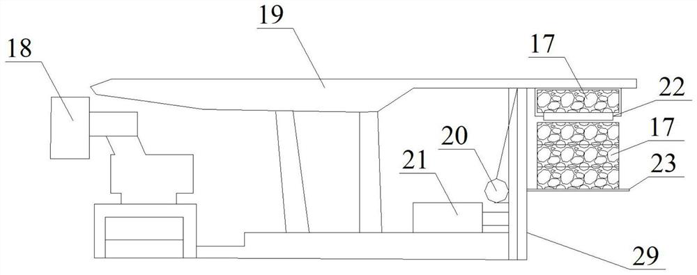
[0028] see image 3 and Figure 4 , the compression block filling system is mainly a special push-in block type filling support. The front part of the support is basically the same as the front part of the conventional support. They are all composed of shearer 18, hydraulic support 19, conveyor and other mechanisms. The rear part of the support is It is specially made for pushing into blocks, and mainly includes devices such as a horizontally telescopic push plate 24, a mobile platform 23, a conveyor 22 behind the frame, and a mobile platform lifting column 29. The composition and parameters of the conveyor 22 behind the frame are basically the same as those of the aforementioned filling and compression block conveyor, suspended on the back and upper side of the hydraulic support 19, connected with the top beam of the hydraulic support 19, and the height from the top beam is in the range of 35-45cm to ensure the filling and compression The blocks 17 can smoothly pass through ...

Embodiment 2

[0030] The specific filling method is as follows:

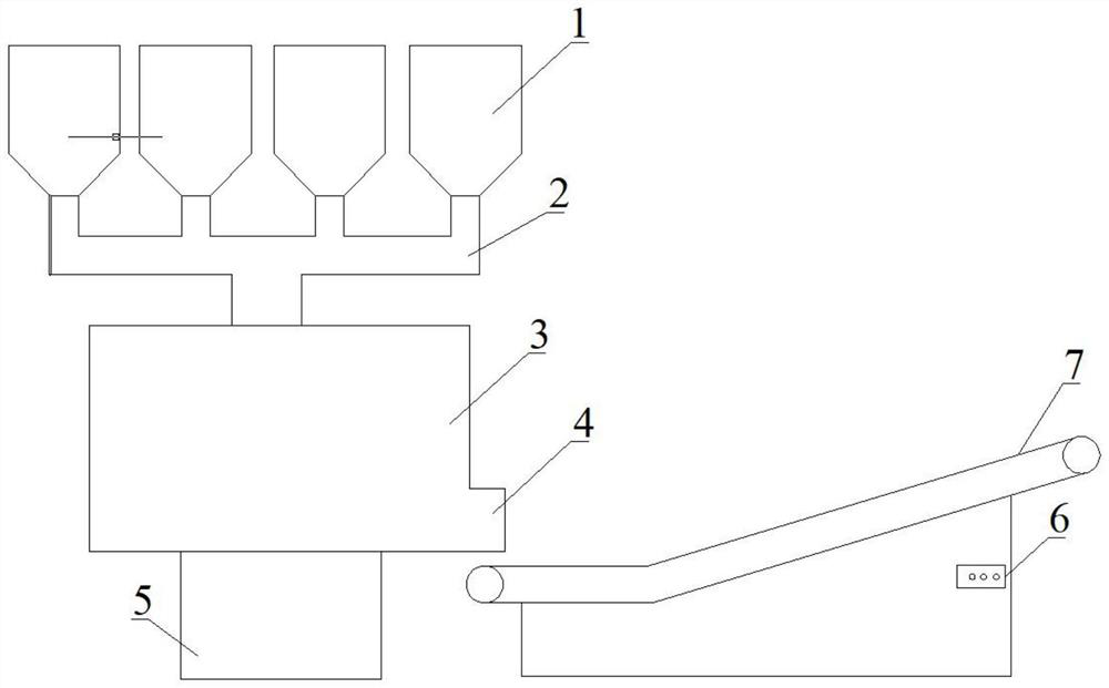
[0031] Process 1: Put the filling material 16 in each material storage bin 1 into the material mixing tank 3 according to a certain ratio, add a certain amount of water, start the mixer 5 to fully stir the mixed material, and the mixed filling material 16 passes through the belt The machine 7 is transferred to the filling material 16 compression molding system. The filling material 16 in the material mixing barrel should be continuously in a stirring state, and the filling material 16 in the mixing barrel 3 should not be less than 1 / 3 of the barrel volume during the production process of the filling compressed block 17, so as to avoid affecting the follow-up work progress.

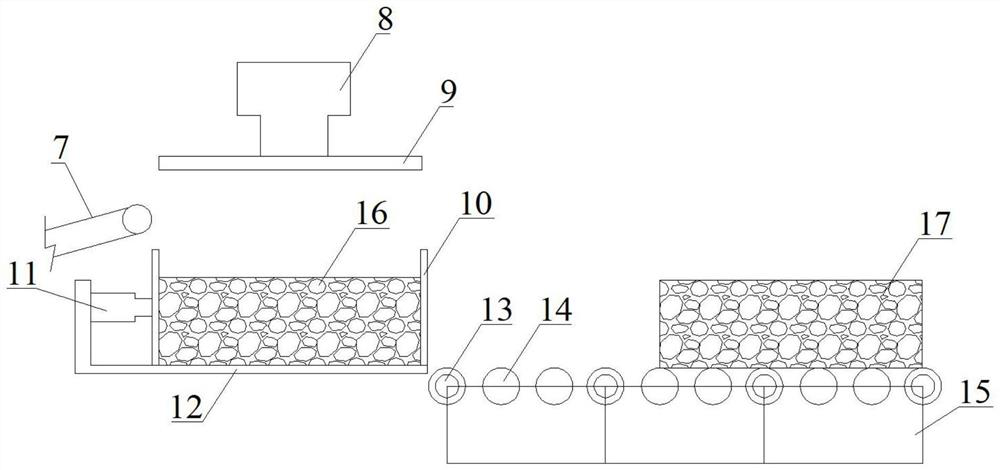
[0032] Process 2: adjust the size of the compression molding box 12, turn on the control switch 6 at the tail of the belt conveyor 7, put the filling material 16 into the compression molding box 12 where the bottom and surrounding steel plates are fixed, ...


PUM


Abstract

The invention discloses an underground compressed block stacking type filling system and method, and aims to improve the compactness of a goaf filling body. The filling system comprises a filling material preparation system, a compression molding system, a filling compressed block conveying system, a goaf block filling system and equipment used in all the systems. The compressed block stacking type filling method is characterized in that the filling system, the filling equipment and the technological process of the filling system are matched with one another according to a certain space-time sequence, the method specifically and mainly comprises the steps of preparation of a filling material, compression molding of filling compressed blocks, conveying of the filling compressed blocks, piling of the filling compressed blocks in a goaf, guniting reinforcement and the like. According to the method, the filling material is compressed and formed in advance to be prefabricated into the high-compactness compressed filling blocks, the compression amount of the filling body under the action of a goaf roof is reduced, the problems that in the conventional solid filling process, the goaf filling body is low in compactness, poor in roof control effect and the like are well solved, and goaf dense filling is achieved.

Description

technical field [0001] The invention belongs to the technical field of solid filling green mining in the coal industry. Background technique [0002] Solid filling technology has become an important green mining technology to solve the "three-down coal pressing" and improve the environment of mining areas. It has been widely used because of its social, economic and environmental benefits. In solid filling, the general method is to transport the gangue-based solid filling mixed material to the working face through the backfill conveyor. Tamp the material. At present, there are corresponding public information on the method of solid filling mining, system composition and filling technologies such as mining, selection and filling + x, such as a mining mode of mining, selection and filling + x mining (notice number: CN109209379A) ​​and so on. This method has been applied in Hebei, Shandong and other mines. However, in the application process, it was found that after the gangu...

Claims


Application Information

Patent Timeline
IPC IPC(8): E21F15/00E21F15/06E21D23/04
Inventor 赵新元杨科魏祯张继强姬健帅王金江陈瑞意
Owner ANHUI UNIV OF SCI & TECH
Learn More