Carbon fiber composite material structure battery and management method

A composite material and carbon fiber technology, applied in the direction of secondary batteries, battery electrodes, structural parts, etc., can solve the problems of structural battery charge and discharge management, flexible electrical configuration, failure detection and reconfiguration design research less, affecting series and parallel unit groups Application, battery unit overshoot and other issues, to achieve a wide range of application prospects and commercial value, realize intelligent application and management, and achieve the effect of battery reconstruction

Active Publication Date: 2021-04-16
BEIHANG UNIV
View PDF2 Cites 1 Cited by
  • Summary
  • Abstract
  • Description
  • Claims
  • Application Information

AI Technical Summary

Problems solved by technology

The working mechanism determines that the voltage and current of such battery cells are low, and most of them can only be used as auxiliary power components, such as providing LED lighting, etc.; and the overall composite material structure is used as a battery cell, if the structure body is partially damaged or fails , will affect the performance of the overall battery unit; in addition, different battery units cannot be flexibly connected in series and parallel. During the charging process, there is a voltage difference between different battery units. If the control is unbalanced, it will cause dangerous situations such as overshoot of the battery unit. ; If a battery unit fails, such as the voltage is too low or too high, it will affect the application of the entire series-parallel unit group
[0005] At present, the research on carbon fiber composite structural batteries mainly focuses on the surface activation modification of carbon fiber materials and the improvement of the conductivity of solid electrolytes, as well as the balanced and optimal design of the mechanical properties of the overall structure. , failure detection and refactoring design, etc.

Method used


Image

  • Carbon fiber composite material structure battery and management method
  • Carbon fiber composite material structure battery and management method
  • Carbon fiber composite material structure battery and management method

Examples


Embodiment Construction

[0040] In order to make the purposes, technical solutions and advantages of the embodiments of the present invention clearer, the technical solutions in the embodiments of the present invention will be clearly and completely described below with reference to the accompanying drawings in the embodiments of the present invention. Obviously, the described embodiments These are some embodiments of the present invention, but not all embodiments. Based on the embodiments of the present invention, all other embodiments obtained by those of ordinary skill in the art without creative work fall within the protection scope of the present invention.

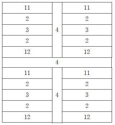
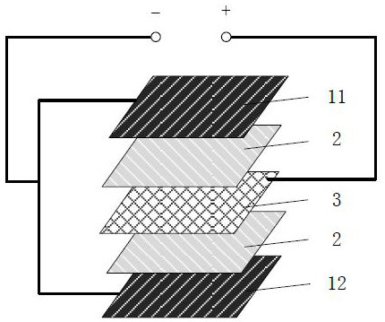
[0041] As shown in FIG. 1( a ) and FIG. 1( b ), a carbon fiber composite material structure battery provided by an embodiment of the present invention includes: a plurality of battery cells. Wherein, each battery unit includes a positive electrode, a negative electrode and a solid electrolyte resin matrix. The positive electrode includes a ...


PUM


Abstract

The invention relates to a carbon fiber composite material structure battery and a management method. The carbon fiber composite material structure battery comprises a plurality of battery units, each battery unit comprises a positive electrode, a negative electrode and a solid electrolyte resin matrix, and the adjacent battery units are separated by an insulating barrier film; according to the management method of the carbon fiber composite material structure battery, the serial and parallel electrical connection relationship of each battery unit in the carbon fiber composite material structure battery is set through the programmable battery controller, the voltage of the battery units is detected, the voltage balance control is performed on the battery units in the charging process, and when the parallel unit groups fail, the battery units are charged. Therefore, the unit group can be cut off through a bypass switch and removed from the series electrical relationship, the charging voltage of the whole battery is reduced, battery reconstruction is realized, and unnecessary loss is reduced.

Description

technical field [0001] The invention relates to the technical field of batteries and battery management, in particular to a carbon fiber composite material structure battery and a management method. Background technique [0002] Carbon fiber has the advantages of high strength, high modulus and light weight. Carbon fiber reinforced resin matrix composites are widely used in aerospace and other fields. Carbon fiber not only has excellent mechanical properties, but also has excellent electrical conductivity and inherent characteristics of carbon materials. It also has two functions of structural bearing and electricity storage, which can further promote the development of lightweight composite structures. [0003] Batteries made of carbon fiber resin-based composites, also known as composite-structured batteries, rely primarily on metal ions, such as lithium ions, to move between the positive and negative electrodes of the battery. The working mechanism of charging and discha...

Claims


Application Information

Patent Timeline
Patent Type & Authority Applications(China)
IPC IPC(8): H01M10/058H01M10/0525H01M10/04H01M4/133H01M4/134H01M10/42H01M10/48H02J7/00
CPCY02E60/10Y02P70/50
Inventor 叶金蕊李世超孙涛
Owner BEIHANG UNIV
Why Eureka
Try Eureka