High-precision film thickness measuring system and method

A measurement system, high-precision technology, applied in the direction of measurement devices, ion implantation plating, coating, etc., can solve problems such as poor reliability, increase in the oscillation frequency of quartz crystals, and affect the optical characteristics of products, so as to avoid power failure and reliable The effect of transmission

Pending Publication Date: 2021-04-20
光芯薄膜(深圳)有限公司
View PDF6 Cites 2 Cited by
  • Summary
  • Abstract
  • Description
  • Claims
  • Application Information

AI Technical Summary

Problems solved by technology

The rotation of the wafer probe brings the following problems: 1) The original water-cooled part of the wafer probe is not suitable for rotating work, resulting in the frequency of the quartz crystal being greatly affected by temperature
During the coating process, with the release of heat from the sputtering source, the temperature of the vacuum chamber gradually increases, and the increase in chamber temperature will lead to an increase in the oscillation frequency of the quartz crystal, which will directly affect the accuracy of film thickness measurement
2) There is a problem in data transmission between the film thickness gauge in motion and the static industrial computer outside the vacuum chamber
The existing scheme (CN104131261B) uses a copper ring-carbon brush mechanism to realize power introduction, and uses WIFI to realize film thickness data transmission, but WIFI transmission has poor reliability in interference environments, and signal interruption will cause the host to fail to obtain film thickness data within a few seconds. When the film processing is about to end, the deposition cannot be stopped in time, and the film thickness is deposited several nanometers, which seriously affects the optical characteristics of the product.
[0006] After research and analysis, because the wafer probe is installed on the workpiece frame, when the wafer probe rotates with the workpiece frame, it can only receive the deposited material intermittently. When the probe rotates close to the sputtering source, the thermal shock of the instantaneous sputtering source will cause the quartz crystal frequency Increased, causing the film thickness meter to incorrectly measure as a decrease in film thickness

Method used


Image

  • High-precision film thickness measuring system and method
  • High-precision film thickness measuring system and method
  • High-precision film thickness measuring system and method

Examples


Embodiment 1

[0038] Embodiment 1 (horizontal sputtering):

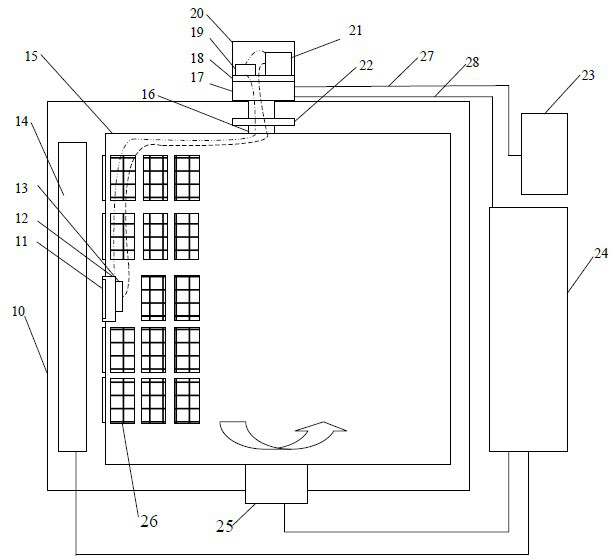
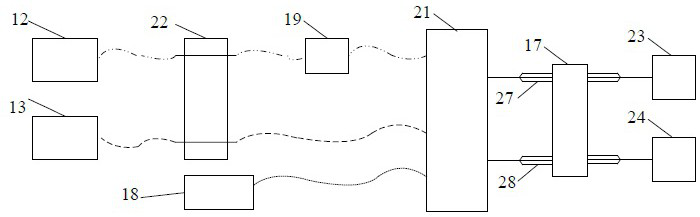
[0039] Such as figure 2Shown is a vertical rotary magnetron sputtering vacuum equipment, including a vacuum chamber 10, a quartz crystal 11, a wafer probe 12, a temperature sensor 13, multiple sets of sputtering targets 14, a rotating workpiece holder 15, a rotating shaft 16, a slip ring 17, Encoder 18, oscillation package 19, film thickness gauge mounting bracket 20, film thickness gauge 21, vacuum feed flange 22, industrial computer 23, electric control cabinet 24, rotating motor 25, workpiece 26.

[0040] The film thickness measurement system includes: quartz crystal 11, wafer probe 12, oscillation package 19, film thickness gauge 21, film thickness gauge mounting bracket 20, temperature sensor 13, encoder 18, slip ring 17, supercapacitor and vacuum feed flange twenty two.

[0041] The quartz crystal 11 is installed in the wafer probe 12 , installed on the vertical surface of the workpiece holder 15 , and rotates with the wo...

Embodiment 2

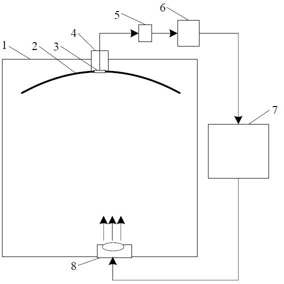
[0052] See Figure 4 , is a schematic diagram of a vertical sputtering structure according to another embodiment of the present invention. The quartz crystal 11 is installed in the wafer probe 12 , installed on the horizontal plane of the workpiece holder 15 , and rotates with the workpiece holder 15 . The coaxial cable of the wafer probe 12 is connected to the oscillating package 19 through the vacuum feeding flange 22 , and the oscillating package 19 is connected to the film thickness gauge 21 through the coaxial cable. The oscillating package 19 and the film thickness gauge 21 are installed in the film thickness gauge mounting bracket 20 outside the vacuum chamber. The film thickness gauge mounting bracket 20 is set on the upper end of the workpiece rack rotating shaft 16, rotates with the workpiece rack 15, and remains relatively stationary with the wafer probe 12 . A rotary motor 25 is installed on the top of the cavity 10 to drive the workpiece holder 15 to rotate horiz...


PUM

PropertyMeasurementUnit
lengthaaaaaaaaaa
lengthaaaaaaaaaa

Abstract

Disclosed is a high-precision film thickness measuring system and method. According to the system, a film thickness meter, an oscillation bag, an encoder and a slip ring are mounted at the top of a rotating shaft of a workpiece frame outside a vacuum cavity, a wafer probe, a quartz crystal and a temperature sensor are mounted on the surface of the workpiece frame inside the vacuum cavity, signals of the wafer probe and the temperature sensor are led out through a vacuum feed-in flange, and the rotating shaft of the workpiece frame drives the components to rotate horizontally. The film thickness meter selects the optimal test position of the quartz crystal according to data of the encoder, performs temperature calibration on the frequency of the quartz crystal according to data of the temperature sensor, accurately calculates real film thickness by using the calibrated frequency, and realizes data transmission with a static industrial personal computer outside the cavity through the slip ring. Therefore, accurate measurement of the film thickness during rotary coating is realized, the influence of temperature is effectively eliminated, and reliable data transmission between moving and non-moving components is ensured.

Description

technical field [0001] The invention relates to the technical field of vacuum coating, in particular to the field of vacuum coating using quartz crystals to detect film thickness. Background technique [0002] During vacuum material surface treatment or vacuum coating, it is usually necessary to monitor the thickness of each layer of film in real time. For example, when coating optical film products, precise control of film thickness is particularly important to ensure the performance of optical films. At present, in the vacuum coating process, there are mainly three methods for controlling the film thickness. The first is the coating time control method, that is, the deposition rate under certain conditions is calculated in advance, and then the deposition time of the film is controlled, and the thickness of the film is obtained by multiplying the deposition rate by the time. The second is the quartz crystal film thickness detection method, which is to calculate the qualit...

Claims


Application Information

Patent Timeline
Patent Type & Authority Applications(China)
IPC IPC(8): C23C14/54C23C14/35C23C14/24G01B17/02
Inventor 夏禹曹永盛郭杏元
Owner 光芯薄膜(深圳)有限公司
Why Eureka
Try Eureka