
Sintering machine tail high-temperature smoke synergistic trapping device and method thereof

A soot and high temperature technology is applied in the field of high-temperature soot-efficiency trapping devices at the tail of a sintering machine, which can solve the problems of strong lifting effect, large volume of high-temperature flue gas, and unreasonable structure of dust hood.

Pending Publication Date: 2021-04-20
CENT RES INST OF BUILDING & CONSTR CO LTD MCC GRP +1
View PDF0 Cites 0 Cited by
  • Summary
  • Abstract
  • Description
  • Claims
  • Application Information

AI Technical Summary

Problems solved by technology

[0004] Under the ultra-low emission requirements of the current environmental protection standards, most iron and steel enterprises have designed a larger rated system air volume in order to make the dust emission concentration of the dust removal system at the sintering machine tail reach the standard, resulting in a huge energy consumption; the old dust removal hood structure is not Reasonable, the volume of the hood is small, but the volume of high-temperature flue gas is large, and the positive pressure inside the hood is serious, forcing high-temperature smoke and dust to emerge from the gap and front end of the hood, seriously polluting the workplace environment; The structure adopts the rear side suction method, which has low collection efficiency for high-temperature smoke and dust; a large amount of wild wind is mixed into the dust removal system from the front end of the dust removal hood, which also causes great energy consumption

Method used


Image

  • Sintering machine tail high-temperature smoke synergistic trapping device and method thereof
  • Sintering machine tail high-temperature smoke synergistic trapping device and method thereof
  • Sintering machine tail high-temperature smoke synergistic trapping device and method thereof

Examples


Embodiment approach

[0050] According to another specific embodiment of the present invention, another device and method for synergistically collecting high-temperature smoke and dust at the tail of a sintering machine are provided, including the following steps:

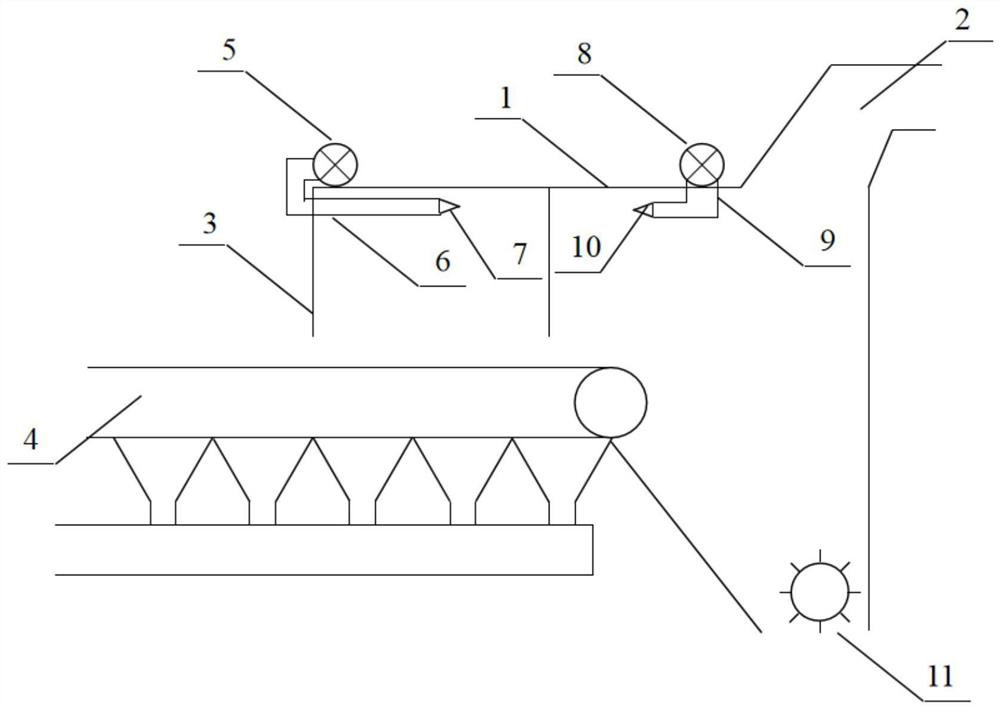
[0051] S1: Feeding, the sintered ore is transported to 2 to 3 trolleys at the tail of the sintering machine through the sintering trolley 4, and the sintering ore is covered by the expansion cover 3 and the tail cover 1;

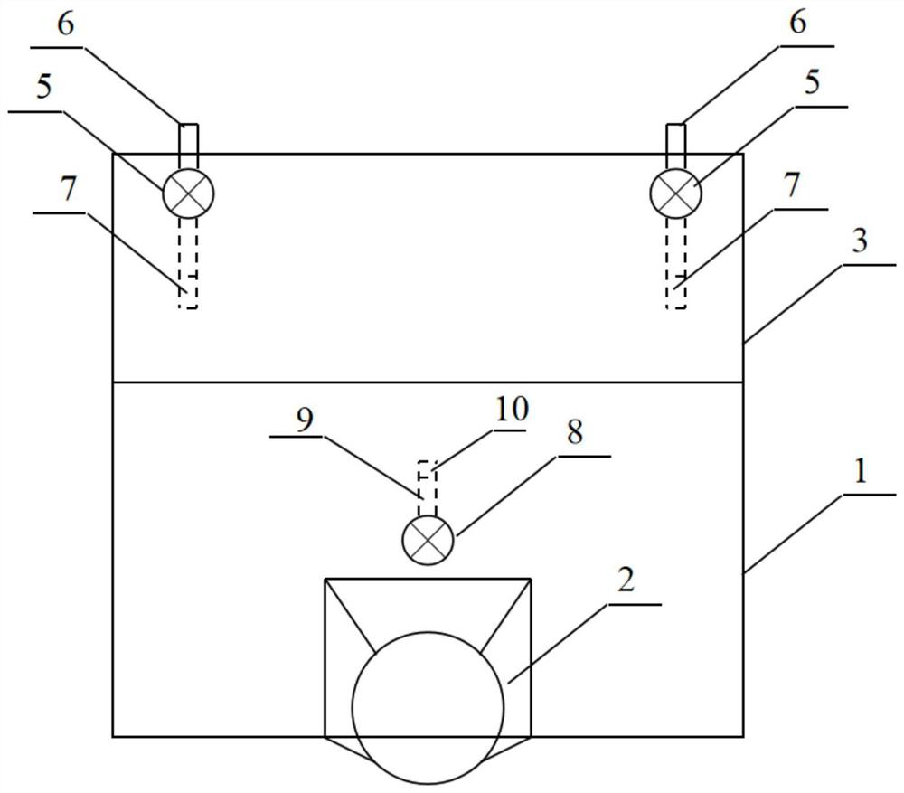
[0052] S2: Jet flow, the air flow ejected from the forward jet flow subsystem and the reverse jet flow subsystem of the jet jet system together form an air curtain to form a directional vortex at the rear of the cover, and the air curtain covers the sintering machine within the attenuation distance end;

[0053] S3: crushing, the sintered ore falls and is crushed by the single roll crusher 11, generating high-temperature smoke and dust during crushing;

[0054] S4: Suction and dust removal, the suction hood 2 connect...


PUM


Abstract

The invention provides a sintering machine tail high-temperature smoke synergistic trapping device and a method thereof. The sintering machine tail high-temperature smoke synergistic trapping device is provided with a machine tail cover, a sintering trolley, an air suction cover, a single-roller crusher, an expansion cover and an ejection flow system, sinter falls down and is crushed by the single-roller crusher to generate high-temperature smoke, and a cover body of the expansion cover extends towards a machine head on the basis of the machine tail cover. The air suction cover is arranged above the rear portion of the machine tail cover, and the ejection flow system enables high-temperature smoke to form directional vortexes in the cover so as to flow into the tail portion of the sintering trolley and prevent the smoke from escaping from the front section of the cover body. According to the sintering machine tail high-temperature smoke synergistic trapping device and the method thereof, the air volume of a dust removal system can be effectively reduced, the trapping efficiency of the high-temperature smoke dust is improved, the smoke dust is prevented from escaping, the ultralow emission requirements of post environment and organized emission are met, and meanwhile, the production condition of the sinter is improved to a certain extent, and cost reduction and efficiency improvement are achieved.

Description

technical field [0001] The invention relates to the field of sintering high-temperature smoke and dust collection and dust removal, in particular to a sinter tail high-temperature smoke and dust synergistic collection device and method thereof. Background technique [0002] The sintering production process is that raw materials such as concentrate powder, limestone, lime and other fuels are mixed with crushed coke, anthracite and other fuels according to a certain ratio, and then the materials are placed on the head of the sintering table. It is broken naturally by its own gravity, and then crushed by a single-roller crusher. After being screened in a chute, it enters a ring cooler to cool down. Finally, the cooled sinter is screened for whole grains and sent to the sintered product warehouse through a belt. The blast furnace ironmaking method is used. [0003] The smoke and dust at the tail of the sintering machine are mainly generated in the discharge box at the tail of t...

Claims


Application Information

Patent Timeline
IPC IPC(8): F27D17/00
Inventor 王珲娄可宾张璞朱晓华王琪琪杨雅娟闫威卓王天莹
Owner CENT RES INST OF BUILDING & CONSTR CO LTD MCC GRP
Learn More