A kind of LC composite mems pressure sensor and preparation method thereof

A pressure sensor and composite technology, applied in the direction of instruments, measuring force, measuring devices, etc., can solve the problems of difficult reliability of the electrodes of MEMS capacitive pressure sensors, and achieve the effect of simple structure, simple preparation process and wide application range

Active Publication Date: 2022-04-29
NANJING GAOHUA TECH
View PDF21 Cites 0 Cited by
  • Summary
  • Abstract
  • Description
  • Claims
  • Application Information

AI Technical Summary

Problems solved by technology

[0003] In order to solve some problems existing in the pressure sensor in this field, the present invention proposes an LC composite MEMS pressure sensor and its preparation method to solve the difficulty in extracting the electrodes of the MEMS capacitive pressure sensor and the reliability problems brought about and to broaden the application of the sensor Scenarios to realize pressure detection in wireless passive scenarios

Method used


Image

  • A kind of LC composite mems pressure sensor and preparation method thereof
  • A kind of LC composite mems pressure sensor and preparation method thereof

Examples


Embodiment 1

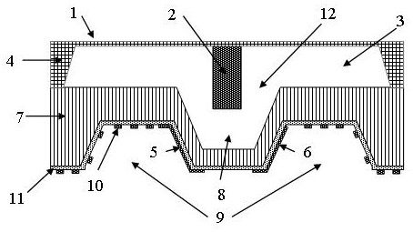
[0037] like Figure 1-2 As shown, the LC composite MEMS pressure sensor proposed by the present invention includes a stacked first substrate 4 and a second substrate 7;

[0038] A pressure sensitive film 1 is formed on the upper surface of the first substrate 4; a first groove 3 is formed on the lower surface of the first substrate 4 opposite to the pressure sensitive film 1 by etching;

[0039] An LC sensitive body 2 is arranged on the lower surface of the pressure sensitive film 1, and the LC sensitive body 2 is located in the first groove 3;

[0040] The second groove 8 is arranged on the upper surface of the second substrate 7, and forms a vacuum chamber 12 with the first groove 3;

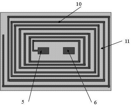
[0041] The third groove 9 is arranged on the lower surface of the second substrate 7 around and spaced apart from the second groove 8;

[0042] The inductor coil layer 10 is disposed on the bottom surface of the third groove 9 and the sidewall on one side away from the second groove 8 .

[...

Embodiment 2

[0062] The present invention also proposes a preparation method of an LC composite MEMS pressure sensor, specifically, the preparation method comprises the following steps:

[0063] a. Select a 500 μm thick N-type (100) single crystal silicon wafer as the first substrate 4, and obtain a first groove 3 with a depth of, for example, 480 μm and a thickness of, for example, 20 μm by photolithography and KOH anisotropic wet etching The pressure sensitive membrane 1;

[0064] b. Install the LC sensitive body 2 on the lower surface of the pressure sensitive film 1 by assembling, the LC sensitive body 2 is, for example, a yttrium iron pomegranate block, and its size is, for example: length×width×height=200 μm×200 μm×600 μm;

[0065] c. Select a 500 μm thick N-type (100) single crystal silicon wafer as the second substrate 7, and carry out photolithography and KOH anisotropic wet etching on the upper surface of the second substrate 7 to obtain a depth of, for example, 400 μm, A second...


PUM

PropertyMeasurementUnit
thicknessaaaaaaaaaa
thicknessaaaaaaaaaa
thicknessaaaaaaaaaa

Abstract

The present invention proposes an LC composite MEMS pressure sensor and a preparation method thereof. The pressure sensor includes: a stacked first substrate and a second substrate; a pressure sensitive film arranged on the upper surface of the first substrate; a groove, arranged on the lower surface of the first substrate, opposite to the pressure sensitive film; an LC sensitive body, arranged on the lower surface of the pressure sensitive film, located in the first groove; the second a groove, arranged on the upper surface of the second substrate, forming a vacuum chamber with the first groove; a third groove, arranged on the lower surface of the second substrate surrounding and spaced apart from the second groove Surface: an inductor coil layer, disposed on the bottom surface of the third groove and a side wall away from the second groove. Under the action of environmental pressure, both L and C of the sensor will change, and the change trend is the same, so it has high sensitivity.

Description

technical field [0001] The invention relates to the field of micro-electromechanical system MEMS, in particular to an LC composite MEMS pressure sensor and a preparation method thereof. Background technique [0002] The pressure sensor is mainly used for the measurement of environmental pressure. It has been developed for many years. It is widely used in the fields of national defense, military, industry, agriculture and medical treatment, and is currently the most common type of sensor. MEMS pressure sensors mainly include two types of MEMS piezoresistive pressure sensors and MEMS capacitive pressure sensors. Compared with MEMS piezoresistive pressure sensors, MEMS capacitive pressure sensors have the advantages of small temperature drift, so they are favored by people. The sensitive capacitance of the existing MEMS capacitive pressure sensor is mainly composed of a fixed electrode, a movable electrode and a cavity. Under the action of environmental pressure, the distance ...

Claims


Application Information

Patent Timeline
Patent Type & Authority Patents(China)
IPC IPC(8): G01L1/14
Inventor 李维平管武干兰之康
Owner NANJING GAOHUA TECH
Why Eureka
Try Eureka