
A sintering machine flue gas condensation dust removal and demisting device

A technology of demisting device and flue gas condensation, applied in combination device, steam condensation, climate sustainability, etc., can solve the problems of affecting equipment, inability to guarantee water balance, and high power consumption for operation

Active Publication Date: 2022-07-05
山东中航天业科技有限公司
View PDF15 Cites 0 Cited by
  • Summary
  • Abstract
  • Description
  • Claims
  • Application Information

AI Technical Summary

Problems solved by technology

[0007] There are problems in the existing technology: first, the water used for cooling is in direct contact with the high-temperature flue gas, which increases the amount of mist droplets in the flue gas while reducing the temperature of the flue gas, and increases the demisting pressure of the subsequent demister, resulting in smoke Water in the air is serious, affecting the back-end equipment
The second is that the water collecting tray increases the resistance of the flue gas, resulting in high fan output requirements and high operating power consumption
Fourth, the water spray cooling causes the water consumption of the system to increase a lot, and the water balance of the whole system cannot be guaranteed
Fifth, due to the characteristics of sintering flue gas, the traditional demisting device is easy to block. Once blocked, the device can only be repaired after the unit is shut down and no flue gas passes through.
[0008] In summary, there are obviously inconveniences and defects in the actual use of the existing technology, so it is necessary to improve

Method used


Image

  • A sintering machine flue gas condensation dust removal and demisting device
  • A sintering machine flue gas condensation dust removal and demisting device
  • A sintering machine flue gas condensation dust removal and demisting device

Examples


Embodiment Construction

[0031] In order to make the objectives, technical solutions and advantages of the present invention more clearly understood, the present invention will be described in further detail below with reference to the accompanying drawings and embodiments. It should be understood that the specific embodiments described herein are only used to explain the present invention, not for The invention is limited.

[0032] It should be noted that, in the description of the present invention, the terms “upper”, “lower”, “left”, “right”, “inner”, “outer” and other terms indicated in the direction or the positional relationship are based on the drawings. The direction or positional relationship shown is only for the convenience of description, rather than indicating or implying that the device or element must have a specific orientation, be constructed and operated in a specific orientation, and therefore should not be construed as a limitation of the present invention.

[0033] In addition, it...


PUM


Abstract

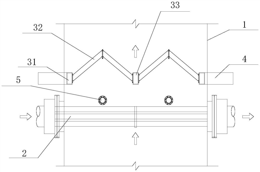
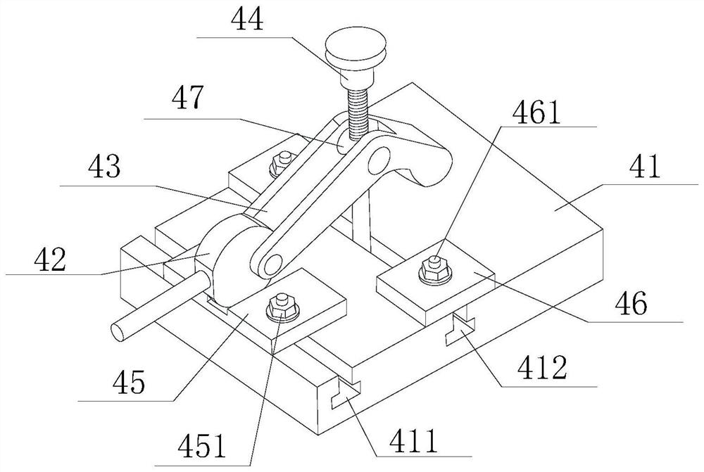
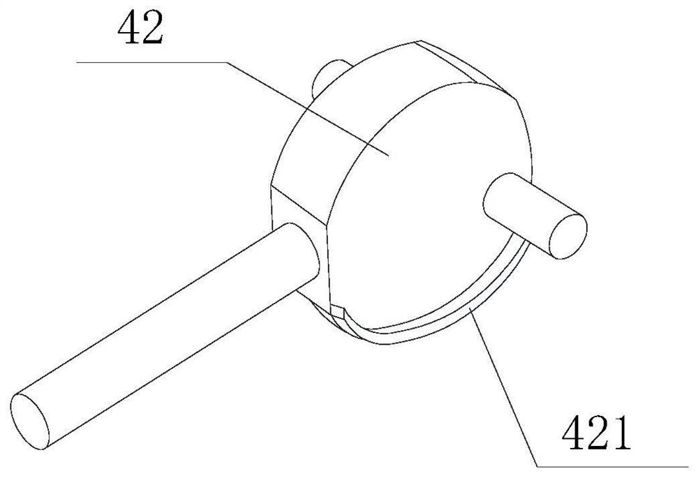
The invention is applicable to the technical field of dust and mist separation, and provides a sintering machine flue gas condensation dedusting and demisting device, which includes a flue, a condensation dedusting module, a demisting device and a fixing device. The rinsing device includes a rinsing water pipe and a rinsing nozzle; the defogging device includes a fixed plate, a defogging blade and a structural beam, and the defogging blade is arranged in a V shape; the fixing device includes a base, an eccentric, an extrusion block and a screw, and the base is There are sliding grooves and limit grooves, the eccentric member is provided with an arc-shaped plate, the fixed plate is provided with a groove for accommodating the eccentric member, and the inner side of the groove is provided with a limit column, the limit column abuts the arc-shaped plate, and the extrusion block is bent. Folded and formed, the rotating shaft is sleeved with the screw, and the fixing plate is located under the end of the extrusion block. Thereby, the present invention can effectively realize the dust removal and separation of smoke, improve the separation efficiency, and at the same time facilitate the realization of detection and maintenance.

Description

technical field [0001] The invention relates to the technical field of dust and mist separation, in particular to a device for condensing, dedusting and demisting of flue gas of a sintering machine. Background technique [0002] In 2018, Hebei, Shanxi, Tianjin and other places successively issued documents on the in-depth control of air pollutants in key industries such as iron and steel sintering machines, coking, and coal-fired power plant boilers. The document requires the treatment of gypsum rain and colored smoke plumes, reducing the temperature and moisture content of flue gas emissions through corresponding technologies, collecting moisture in supersaturated water vapor in flue gas, and reducing soluble salts, sulfuric acid mist, organic matter in flue gas. Emissions of condensed particulate matter. [0003] In March 2020, Handan City issued the "Implementation Plan for In-depth Air Pollution Control in Key Industries of Industrial Enterprises in Handan City in 2020"...

Claims


Application Information

Patent Timeline
IPC IPC(8): B01D50/20B01D5/00B01D53/00
CPCB01D53/002B01D5/00B01D50/20Y02P10/25
Inventor 张小琴刘欣张晓东李晓张庆金丁德强
Owner 山东中航天业科技有限公司
Learn More