Continuous casting machine and continuous casting method

A casting machine and transition tube technology, which is applied in the field of continuous casting of copper and copper alloys, can solve problems such as inconvenient docking, short service life of the crystallizer, and inability to monitor the temperature in the furnace, so as to improve the quality of ingots and prolong the service life. The effect of life, simple structure

Inactive Publication Date: 2021-05-04
HANGZHOU HUAGUANG ADVANCED WELDING MATERIALS CO LTD +1
View PDF7 Cites 1 Cited by
  • Summary
  • Abstract
  • Description
  • Claims
  • Application Information

AI Technical Summary

Problems solved by technology

[0002] In the traditional continuous casting method of copper and copper alloys, the crucible of the holding furnace is usually directly connected to the crystallizer in a sealed manner, and the service life of the mold is short; the liquid level in the furnace can only be controlled indirectly by controlling the drawing speed, and the temperature in the furnace cannot be monitored; The surface of the formed ingot is oxidized and needs to be cleaned before use, which is inconvenient to connect with the subsequent process

Method used


Image

  • Continuous casting machine and continuous casting method
  • Continuous casting machine and continuous casting method
  • Continuous casting machine and continuous casting method

Examples


Embodiment Construction

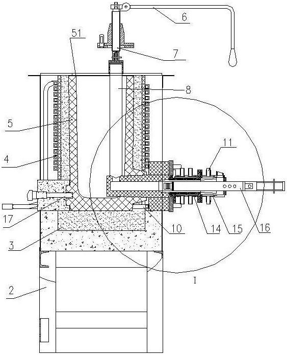
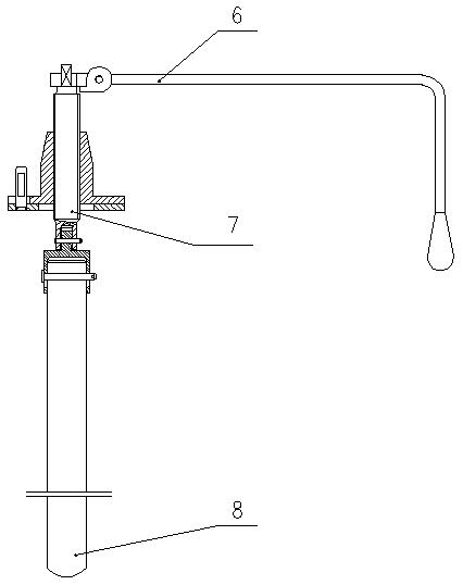
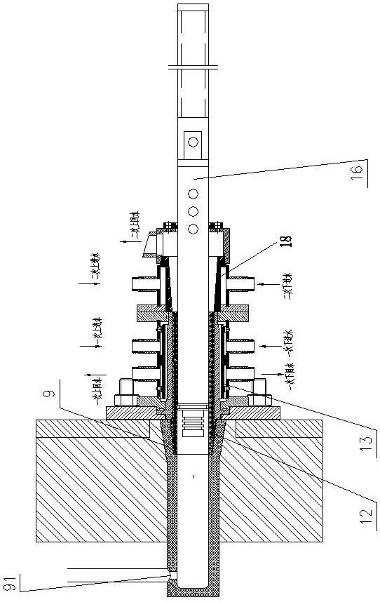
[0020] The present application will be described in further detail below in conjunction with the accompanying drawings and examples. The following examples are explanations of the present application and the present application is not limited to the following examples. The context described in this application is relative to figure 1 In terms of figure 1 Middle left is back, right is front.

[0021] see Figure 1 ~ Figure 4 , the continuous casting machine of the embodiment of the present application includes a workbench 2, a tundish 3, a coil 4, a graphite crucible 5, a handle 6, a rotating shaft 7, a graphite stopper rod 8, a graphite transition pipe 9, an air inlet 10, a crystallizer 11, a graphite Bushing 12, primary water-cooled copper sleeve 13, primary cooling device 14, secondary cooling device 15, dummy rod 16, thermocouple 17, secondary water-cooled copper sleeve 18. The application uses a smelting furnace to melt the raw materials, and the copper alloy liquid is ...


PUM


Abstract

The invention relates to a continuous casting machine and a continuous casting method. The continuous casting machine comprises a workbench, a crystallizer and a dummy bar. The continuous casting machine is characterized in that the continuous casting machine further comprises a tundish, a transition pipe and a thermocouple, the tundish used for storing a solution is arranged on the workbench, the tundish comprises a heater and a crucible surrounded by the heater, and the thermocouple makes contact with the exterior of the crucible; the transition pipe is hermetically connected with the crystallizer, and the transition pipe is a hollow circular pipe; a protective gas supply device communicates with the outer wall of the transition pipe through a gas inlet; the crystallizer comprises a water-cooling copper sleeve and a lining in interference fit with the water-cooling copper sleeve, the dummy bar is arranged between the transition pipe and the crystallizer and is in clearance fit with the crystallizer, and the front end of the dummy bar is connected with a power device. The continuous casting method comprises the following steps of feeding, smelting, slag fishing, refining, opening of the transition pipe through a stopper control mechanism for casting, and secondary water cooling and drawing after casting. The continuous casting device is simple in structure, low in cost, good in casting quality, not prone to being oxidized and capable of achieving continuous production.

Description

technical field [0001] The application relates to a continuous casting machine and a continuous casting method, which are mainly applicable to the continuous casting production of copper and copper alloys. Background technique [0002] In the traditional continuous casting method of copper and copper alloys, the crucible of the holding furnace is usually directly connected to the crystallizer in a sealed manner, and the service life of the mold is short; the liquid level in the furnace can only be controlled indirectly by controlling the drawing speed, and the temperature in the furnace cannot be monitored; The surface of the formed ingot is oxidized and needs to be cleaned before use, which is inconvenient to connect with the subsequent process. Contents of the invention [0003] The purpose of this application is to overcome the deficiencies in the prior art, and provide a low-cost, high-efficiency continuous casting machine and a continuous casting method for continuous...

Claims


Application Information

Patent Timeline
Patent Type & Authority Applications(China)
IPC IPC(8): B22D11/14B22D11/055B22D11/18
CPCB22D11/14B22D11/004B22D11/055B22D11/182
Inventor 何中要马蜓孙海涛左天应陈融
Owner HANGZHOU HUAGUANG ADVANCED WELDING MATERIALS CO LTD
Why Eureka
Try Eureka