
Large three-dimensional detachable similar simulation experiment device for drilling cuttings
A similar simulation experiment, three-dimensional technology, applied in the field of large-scale three-dimensional detachable drill cuttings similar simulation experiment device, can solve the problems of loading rigid plate can not follow, large force at the jack indenter, small size, etc., to avoid The effect of boundary effect, reducing experimental error and improving accuracy
- Summary
- Abstract
- Description
- Claims
- Application Information
AI Technical Summary
Problems solved by technology
Method used
Image

Examples
Embodiment Construction
[0022] The present invention will be further described in detail below in conjunction with the accompanying drawings and specific embodiments.
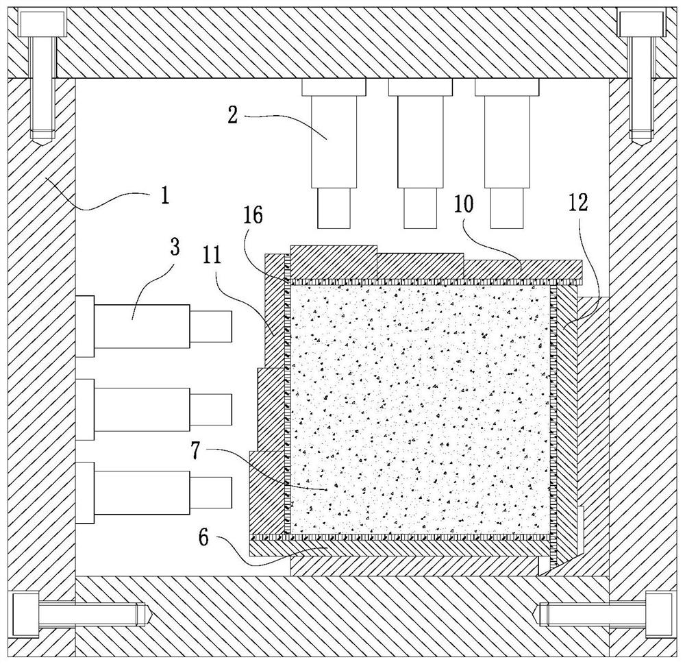
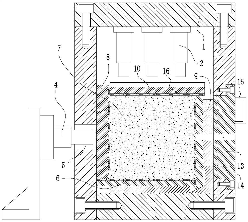
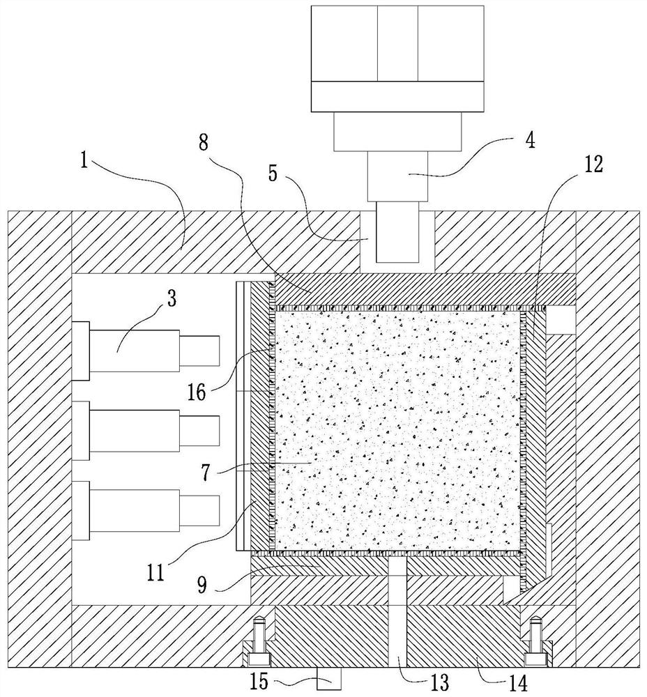
[0023] Such as Figure 1~3 As shown, a large-scale three-dimensional detachable drill cuttings similar simulation experiment device includes a detachable reaction frame 1, a top hydraulic loading cylinder group 2, a side hydraulic loading cylinder group 3 and a rear dynamic load loading cylinder 4; The top hydraulic loading cylinder group 2 is arranged on the lower surface of the top plate of the detachable reaction force frame 1, and the top hydraulic loading cylinder group 2 contains nine top hydraulic loading cylinders, and the nine top hydraulic loading cylinders are all set vertically and adopt Matrix uniform distribution method; the side hydraulic loading cylinder group 3 is arranged on the inner surface of the left side plate or the right side plate of the detachable reaction force frame 1, and the side hydraulic loading cylind...
PUM
 Abstract
Description
Claims
Application Information