
Integrated high-speed polarization controller based on lithium niobate thin film and preparation method

A polarization controller, lithium niobate technology, applied in instruments, nonlinear optics, optics, etc., can solve expensive problems, and achieve the effects of low power consumption, fast response speed, and simple process

Active Publication Date: 2021-05-04
SOUTH CHINA NORMAL UNIVERSITY
View PDF5 Cites 5 Cited by
  • Summary
  • Abstract
  • Description
  • Claims
  • Application Information

AI Technical Summary

Problems solved by technology

[0009] In order to solve the short-distance high-speed communication system and avoid the problem of using expensive high-speed ADC and DSP devices, the present invention proposes a polarization controller based on X-cut thin-film lithium niobate, which has high speed, high precision and small size , easy to integrate, etc.

Method used


Image

  • Integrated high-speed polarization controller based on lithium niobate thin film and preparation method
  • Integrated high-speed polarization controller based on lithium niobate thin film and preparation method
  • Integrated high-speed polarization controller based on lithium niobate thin film and preparation method

Examples


Embodiment 1

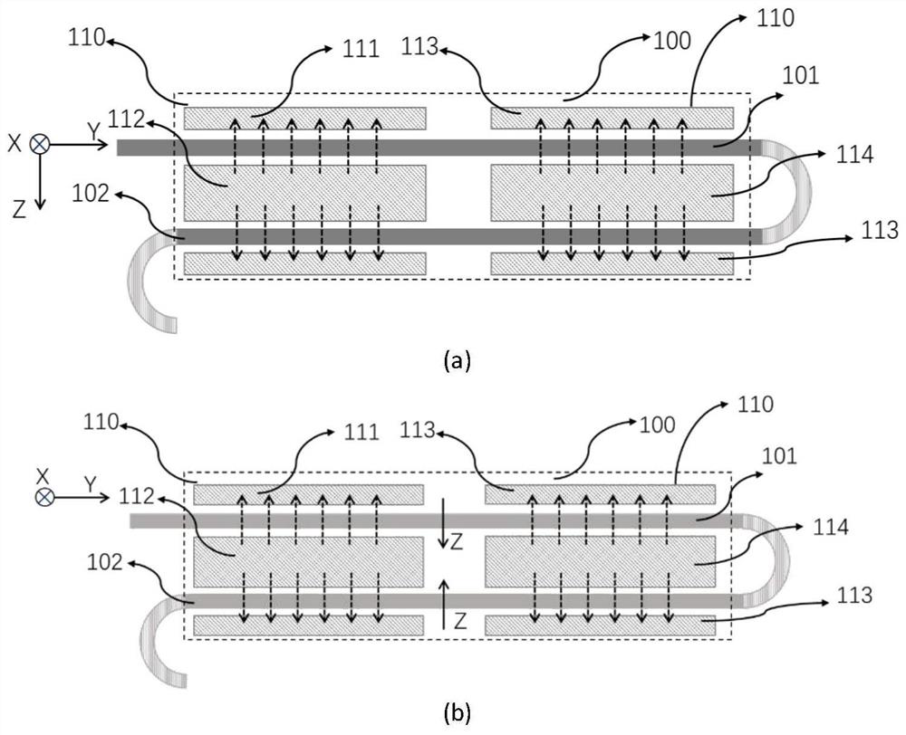
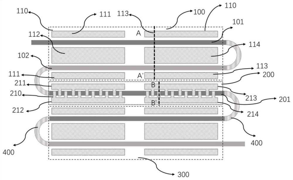
[0072] Such as image 3As shown, it is an embodiment of the present invention, the lower cladding layer 501 and the upper cladding layer 503 of the lithium niobate waveguide are made of silicon dioxide, and the substrate 502 is made of silicon. In this embodiment, the effective refractive indices of the two polarization modes TE and TM in the mode conversion region are not equal, and birefringence exists. In the first phase shifting area 100 and the second phase shifting area 300, the GSG segmented electrodes 110 of the first phase shifting area 100 are located on both sides of the lithium niobate waveguide, and the two polarization modes of TE and TM are controlled under the action of the electric field Ez The phase difference, the cross-sectional schematic diagram is shown in Figure 4 shown. In the mode conversion region 200, in order to realize the conversion of the orthogonal TE / TM mode in the lithium niobate waveguide, it is necessary to introduce off-diagonal elements...

Embodiment 2

[0074] In the lithium niobate waveguide, when the refractive indices of TE and TM are matched, that is, when there is no phase mismatch, the use of periodic electrodes or chirped electrodes can be avoided to match the refractive indices of TE and TM. The schematic diagram of the structure is as follows Image 6 shown. The electrodes in the phase-shifting region are the same as in Embodiment 1, and the electrodes in the mode-converting region can completely switch between the two modes without periodic electrodes due to the matching of TE and TM refractive index. The non-diagonal element of the electric field Ex component can not be zero, the first segment signal electrode 212 of the mode conversion segment electrode 210 of the mode conversion zone segment electrode and the second segment signal electrode 214 of the mode conversion zone segment electrode 214 are located in the lithium niobate waveguide 201 the top of.


PUM


Abstract

The invention discloses a polarization controller based on an X-cut thin film lithium niobate waveguide. The polarization controller comprises a first phase shift region, a mode conversion region, a second phase shift region and a bent waveguide, wherein one end of the first phase shift region is an input end, and the other end is connected with one end of the mode conversion region through the bent waveguide; the first phase shift region and the second phase shift region are composed of lithium niobate straight waveguides which are not subjected to polarization reversal, bent waveguides, lithium niobate straight waveguides which are subjected to polarization reversal and electrodes, the straight waveguides are arranged in the Y direction of a lithium niobate crystal axis, and the electrodes are located on the left side and the right side of the straight waveguides; the other end of the mode conversion region is connected with one end of the second phase shift region through the bent waveguide; the other end of the second phase shift region is an output end for outputting light of the polarization controller; the mode conversion region is composed of a lithium niobate straight waveguide, a bent waveguide and electrodes, and the electrodes are located around the straight waveguide; and the first and second phase shift regions realize a push-pull working mode through polarization reversal part lithium niobate waveguides. The controller has the advantages of high speed, high precision, small size and easiness in integration.

Description

technical field [0001] The invention relates to the technical field of optical communication, specifically an integrated high-speed polarization controller based on an X-cut lithium niobate thin film. Background technique [0002] The explosive growth of data traffic in the information age has put forward higher requirements for data transmission, storage, and processing. Services such as ultra-high-definition video, large-scale games, and cloud services require high-performance, low-cost devices to provide powerful physical Layer support, the optical communication network has become an indispensable part of communication. The upgrade of 5G networks and data centers will accelerate the laying of 40Gbit / s, 100Gbit / s or even higher-speed optical fiber communication networks, and researchers have begun to study 400Gbit / s or even Tbit / s transmission systems. In the field of optical fiber communication, when an optical signal is transmitted in an optical fiber, ideally the polar...

Claims


Application Information

Patent Timeline
Patent Type & Authority Applications(China)
IPC IPC(8): G02F1/03G02F1/035
CPCG02F1/0316G02F1/0353G02F1/0327
Inventor 李炽均郑智文郭昌建陈朋鑫刘柳
Owner SOUTH CHINA NORMAL UNIVERSITY
Learn More