Crop irrigation device for agricultural greenhouse

A technology for watering devices and crops, applied in drinking water devices, agriculture, spray devices, etc., can solve the problems of large labor consumption, easy dehydration of soil and crops, unfavorable crop growth, etc., to reduce consumption, save the use of water resources, good effect

Inactive Publication Date: 2021-05-07
刘义华
View PDF0 Cites 8 Cited by
  • Summary
  • Abstract
  • Description
  • Claims
  • Application Information

AI Technical Summary

Problems solved by technology

[0003] Since the vegetable greenhouse is in a stuffy state, the internal ventilation effect is not good, which leads to the easy dehydration of the soil and crops, which is not conducive to the growth of the crops. Therefore, the staff need to water the soil, and

Method used


Image

  • Crop irrigation device for agricultural greenhouse
  • Crop irrigation device for agricultural greenhouse
  • Crop irrigation device for agricultural greenhouse

Examples


Embodiment 1

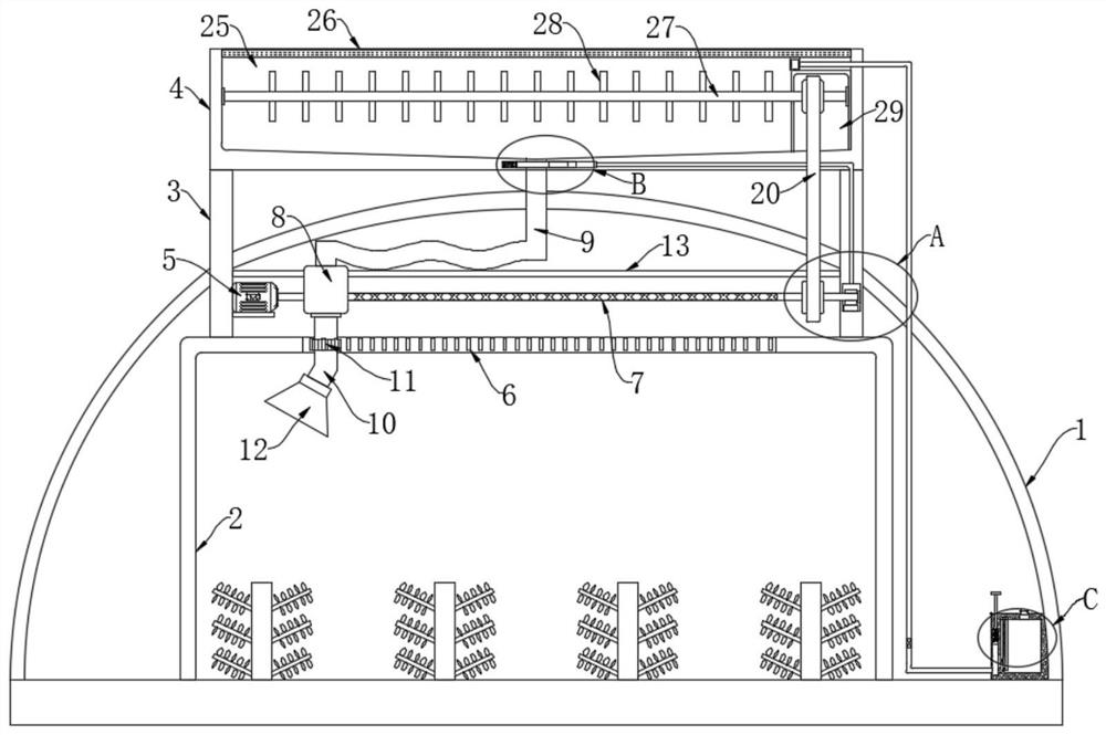
[0027] refer to Figure 1-4 , a crop watering device for agricultural greenhouses, comprising a protective shed 1, a mounting bracket 2 and a storage box 14 are installed in the protective shed 1, the storage box 14 is used to store chemicals, the mounting bracket 2 is located on the left of the storage box 14, and the mounting bracket 2. It consists of two vertical bars and a horizontal bar. The lower ends of the two vertical bars are fixedly connected to the ground. Vegetation is arranged between the two vertical bars. A water collection tank 4 is provided above the protective shed 1. The water collection box 4 The upper end is provided with a collection tank 25, which is used to collect rainwater. The lower end of the water collection tank 4 is fixedly connected with two support bars 3, and the lower ends of the two support bars 3 run through the protective shed 1 and are fixedly connected with the cross bar. The collection tank 25 Filter screen 26 is installed at the notch...

Embodiment 2

[0039] refer to Figure 5-6 , The difference between this embodiment and Embodiment 1 is that a magnetic slide bar 35 for moving up and down is provided in the collection tank 25, and the magnetic slide bar 35 is located below the second rotating bar 27, and a row of stirring bars 28 all have Magnetic, the magnetic slide bar 35 and the adjacent surface of the magnetic stirring bar 28 repel each other at the same pole, so the magnetic slide bar 35 is driven downward, and a plurality of air bags 36 are installed between the lower end of the magnetic slide bar 35 and the inner bottom of the collection tank 25 , the upper ends of the plurality of airbags 36 are provided with liquid ports.

[0040] In this embodiment, when a plurality of stirring rods 28 rotate, when a row of magnetic stirring rods 28 is adjacent to the magnetic sliding rod 35, a downward repulsion force will be given to the magnetic sliding rod 35, so that the magnetic sliding rod 35 squeezes Press a plurality of...


PUM


Abstract

The invention discloses a crop irrigation device for an agricultural greenhouse. The crop irrigation device comprises a protective shed, a mounting support and a storage box are mounted in the protective shed, the mounting support is located on the left side of the storage box, the mounting support is composed of two vertical rods and a transverse rod, vegetation is arranged between the two vertical rods, a water collecting tank is arranged above the protective shed, a collecting groove is formed in the upper end of the water collecting tank, two supporting strips are fixedly connected to the lower end of the water collecting tank, and the lower ends of the two supporting strips penetrate through the protective shed and are fixedly connected with the transverse rod. According to the crop irrigation device for the agricultural greenhouse, greenhouse soil is watered by collecting rainwater, and water resources are saved; and meanwhile, spray heads can rotate, the spraying effect is better, chemicals can be added at any time according to actual needs, and growth of vegetables is better facilitated.

Description

technical field [0001] The invention relates to the field of agricultural production, in particular to a crop irrigation device for agricultural greenhouses. Background technique [0002] Greenhouse planting technology is a relatively common technology. It has good thermal insulation performance and can eat off-season vegetables at any time. It is very popular among people. The construction of vegetable greenhouses is generally based on bamboo and steel. The structural skeleton, and then covered with one or more layers of thermal insulation plastic film, such a simple structure can create a complete space for protecting crops; [0003] Since the vegetable greenhouse is in a stuffy state, the internal ventilation effect is not good, which leads to the easy dehydration of the soil and crops, which is not conducive to the growth of the crops. Therefore, the staff need to water the soil, and many existing greenhouses are watered. The way of watering and drip irrigation, due to ...

Claims


Application Information

Patent Timeline
IPC IPC(8): A01G9/14A01G9/24A01M7/00E03B3/02A01C23/04B05B15/25
CPCA01C23/047A01G9/14A01G9/247A01M7/0025B05B15/25E03B3/02Y02A20/108Y02A40/25
Inventor 刘义华
Owner 刘义华
Why Eureka
Try Eureka