Punching device for machining and producing motor end cover

A technology for motor end caps and drilling devices, which is applied to positioning devices, feeding devices, driving devices, etc., can solve the problems of inability to adjust, low applicability, and low drilling efficiency, so as to ensure drilling efficiency and avoid The effect of low drilling efficiency

Inactive Publication Date: 2021-05-07
BEIHUA UNIV
View PDF0 Cites 3 Cited by
  • Summary
  • Abstract
  • Description
  • Claims
  • Application Information

AI Technical Summary

Problems solved by technology

[0002] The motor refers to an electromagnetic device that realizes the conversion or transmission of electric energy according to the law of electromagnetic induction. Its main function is to generate driving torque as a power source for electrical appliances or various machines. The motor end cover is one of the important parts of the motor. The end cover is the cover of the motor casing. Generally, it is divided into a front cover and a rear cover. It is used to fix and support the motor shaft. Generally speaking, it uses the front and rear end covers of the motor to fix the entire motor through the shaft. In the process, the end cover is usually punched to facilitate the installation and use of the motor end cover, but in the use of the end cover punching device, a single drill bit punching machine is usually used for direct punching, and the efficiency of punching is relatively low. Low, and in the use of some drilling machines that can drill multiple holes at the same time, the length value between the two drill bits is fixed, and cannot be adjusted according to the different drilling positions, and the applicability is low

Method used


Image

  • Punching device for machining and producing motor end cover
  • Punching device for machining and producing motor end cover
  • Punching device for machining and producing motor end cover

Examples


Embodiment Construction

[0034] The following will clearly and completely describe the technical solutions in the embodiments of the present invention with reference to the accompanying drawings in the embodiments of the present invention. Obviously, the described embodiments are only some, not all, embodiments of the present invention. Based on the embodiments of the present invention, all other embodiments obtained by persons of ordinary skill in the art without making creative efforts belong to the protection scope of the present invention.

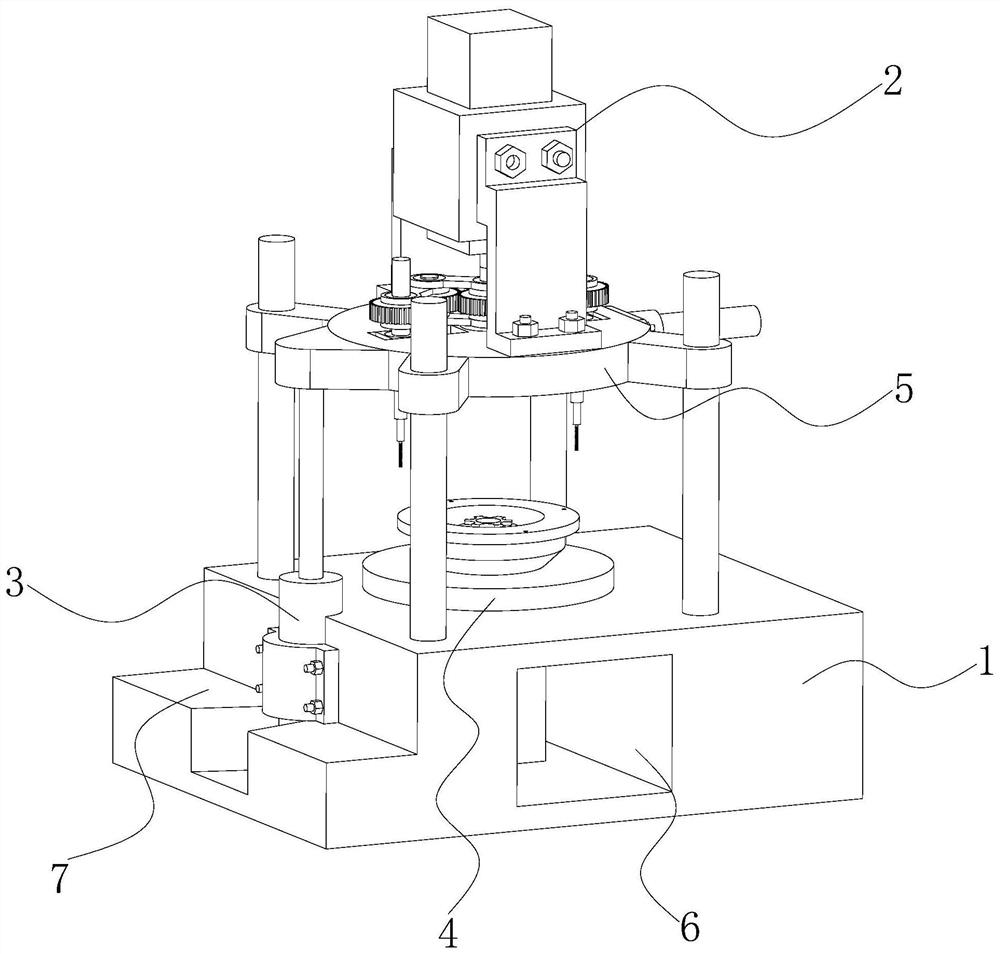
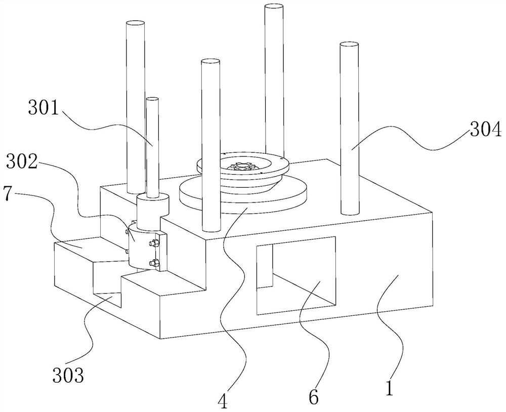
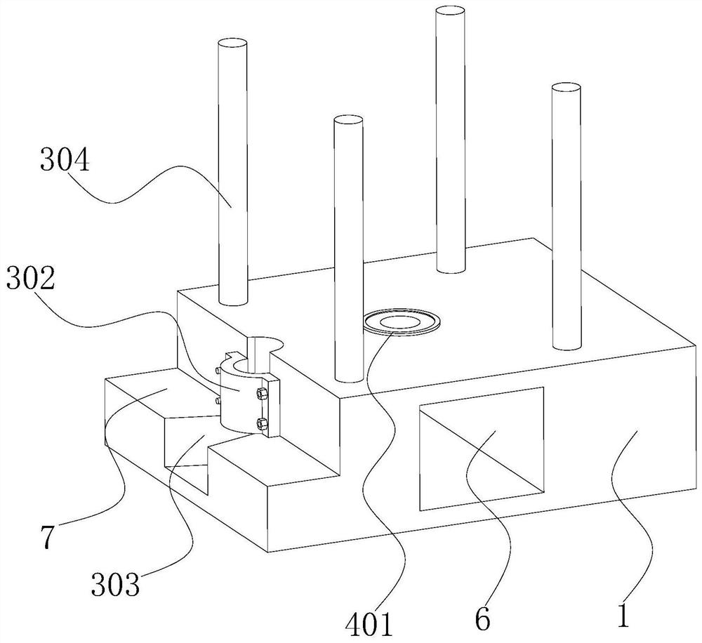
[0035] see Figure 1-11, the present invention provides a technical solution: a punching device for motor end cover processing and production, including a bottom frame 1, a material transfer mechanism 4 is installed on the upper surface of the bottom frame 1, and a height adjustment mechanism is fixedly installed on the left side of the bottom frame 1. Mechanism 3, a top plate 5 is placed above the underframe 1, and a driving punching mechanism 2 is installed ...


PUM


Abstract

The invention discloses a punching device for machining and producing a motor end cover, and relates to the technical field of motor end cover punching. The punching device comprises a bottom frame, a material rotating mechanism is mounted on the upper surface of the bottom frame, a height adjusting mechanism is fixedly mounted on the left side of the bottom frame, a top plate is placed above the bottom frame, and a punching driving mechanism is mounted on the top plate. According to the punching device for machining and producing the motor end cover, a second servo motor operates to drive a driving gear to rotate, the driving gear drives two transmission gears to synchronously rotate in opposite directions, the two transmission gears rotate to drive two driven gears to synchronously rotate, and the rotating direction of the driven gears is the same as that of the second servo motor. Second fixing columns are driven to rotate, drill bits at the bottoms are driven to rotate, the telescopic end of a first electric push rod retracts, the height of the drill bits is reduced, punching treatment is conducted after the drill bits make contact with an end cover body, the two drill bits are driven by a single motor to conduct synchronous rotating punching, and the drilling efficiency can be better guaranteed.

Description

technical field [0001] The invention relates to the technical field of punching motor end caps, in particular to a punching device for processing and producing motor end caps. Background technique [0002] The motor refers to an electromagnetic device that realizes the conversion or transmission of electric energy according to the law of electromagnetic induction. Its main function is to generate driving torque as a power source for electrical appliances or various machines. The motor end cover is one of the important parts of the motor. The end cover is the cover of the motor casing. It is generally divided into a front cover and a rear cover. It is used to fix and support the motor shaft. Generally speaking, it uses the front and rear end covers of the motor to fix the entire motor through the shaft. In the process, the end cover is usually punched to facilitate the installation and use of the motor end cover, but in the use of the end cover punching device, a single drill...

Claims


Application Information

Patent Timeline
IPC IPC(8): B23B39/16B23B47/06B23Q3/06B23Q5/28B23Q5/22
CPCB23B39/16B23Q3/06B23Q5/10B23Q5/22B23Q5/28
Inventor 吴勇
Owner BEIHUA UNIV
Why Eureka
Try Eureka