Cavity-backed circularly polarized patch antenna array with filtering function

A patch antenna and cavity-backed circle technology, which is applied in antenna array, antenna, antenna coupling, etc., to achieve superior filtering characteristics, low manufacturing cost, and easy processing

Active Publication Date: 2021-05-07
HANGZHOU DIANZI UNIV
View PDF6 Cites 6 Cited by
  • Summary
  • Abstract
  • Description
  • Claims
  • Application Information

AI Technical Summary

Problems solved by technology

In these only filter antenna array designs, almost all the attention is focused on the linear polarization filter antenna array, so relatively, the research on the circular polarization filter antenna array can be said to be a blank

Method used


Image

  • Cavity-backed circularly polarized patch antenna array with filtering function
  • Cavity-backed circularly polarized patch antenna array with filtering function
  • Cavity-backed circularly polarized patch antenna array with filtering function

Examples


Embodiment Construction

[0057] The present invention is further analyzed below in conjunction with specific examples.

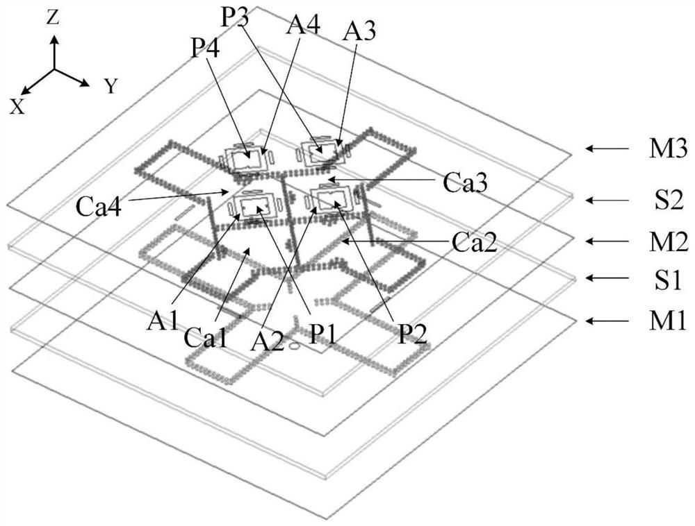
[0058] combine figure 1 , figure 2 and image 3 , a cavity-backed circularly polarized patch antenna array with filtering function, including two layers of Rogers5880 dielectric substrates S1 and S2 with a thickness of 1.575mm and the lower metal surface M1, middle metal surface M2, and upper metal surface M3 of the same size as the dielectric substrate .

[0059] Surrounded by the dielectric substrate S2 are four adjacent substrate-integrated waveguide cavities Ca1-Ca4 with a side length of 23 mm and surrounded by metallized through holes. The diameter of the metallized through hole is 1 mm, which is less than one-tenth of the air wavelength corresponding to the center frequency of the antenna. The center-to-center distance between two adjacent metallized through holes is 1.5 mm. One corner of the cavity was cut off, and the length of the gap was 12.9m. Each of the chambers ...


PUM


Abstract

The invention relates to a cavity-backed circularly polarized patch antenna array with a filtering function. According to the invention, an integrated design of an antenna and a filter is carried out in a single-layer single substrate integrated waveguide cavity, and a wide impedance bandwidth is realized by introducing TM120 and TM210 of a resonant cavity and TM10 and TM01 of a microstrip patch. However, an axial ratio bandwidth is much narrower than an impedance bandwidth. Therefore, in order to further broaden the effective working bandwidth of the antenna, an array design is carried out. Through a rotation sequence feed mode and introduction of a second-order high-pass filter on a dielectric integrated waveguide, the axial ratio bandwidth of the antenna is widened, the antenna gain is improved, and the filtering effect of the antenna is further optimized.

Description

technical field [0001] The invention belongs to the technical field of antennas for wireless communication terminals, and relates to a cavity-backed patch circularly polarized antenna array with a filtering function, which can be used as an antenna for a radio frequency front end of a miniaturized wireless transceiver, and is widely used in mobile communications, satellite communications and radar and other wireless communication systems. Background technique [0002] As we all know, array antennas can be used to increase the gain of the antenna, and for circularly polarized antennas, the array method of feeding in rotation order can effectively expand the axial ratio bandwidth. Circularly polarized patch antennas have a very wide application prospect in modern communication systems due to their significant advantages such as light weight, small size, low profile, easy integration, and ability to resist multipath interference. However, the axial ratio bandwidth of this type...

Claims


Application Information

Patent Timeline
Patent Type & Authority Applications(China)
IPC IPC(8): H01Q1/38H01Q1/52H01Q21/00
CPCH01Q1/38H01Q1/52H01Q21/00
Inventor 罗国清王文磊金华燕张晓红代喜望
Owner HANGZHOU DIANZI UNIV
Why Eureka
Try Eureka