Wireless laparoscope

A laparoscopic and wireless technology, applied in laparoscopy, endoscopy, medical science, etc., can solve problems affecting the operator's degree of freedom of operation, operating instruments to block light, and hindering the development of ultra-minimally invasive laparoscopy.

Pending Publication Date: 2021-05-18
伍端友
View PDF7 Cites 0 Cited by
  • Summary
  • Abstract
  • Description
  • Claims
  • Application Information

AI Technical Summary

Problems solved by technology

[0004] 1. Hand holding the mirror and related physical obstacles: The unique role derived from the existing laparoscopy technology, that is, the assistant on the operating table who specializes in laparoscopy, controls the angle and distance of the laparoscope to provide lighting and surgical vision for the entire operation, and supports There is often a gap between what the mirror hand presents and the wishes of the chief surgeon. To achieve a tacit cooperation requires a considerable amount of time and practical training and running-in, which is an additional labor cost that is difficult to please.
The laparoscope body and its cables have physical obstacles such as crowding, touching, and restrictions on surgical instruments and surgical operations, especially hindering the ultra-minimally invasive development of transumbilical single-site laparoscopy
[0005] 2. Two-dimensional plane surgical field: limited to monocular camera and imaging technology, the field of view of laparoscopy is a two-dimensional plane, lacking depth vision, and requires a longer period of specialized training to adapt, compared with the natural stereoscopic vision o

Method used


Image

  • Wireless laparoscope
  • Wireless laparoscope
  • Wireless laparoscope

Examples


Embodiment Construction

[0046] The specific embodiments of the present invention will be described below in conjunction with the accompanying drawings.

[0047] The symbols and components involved in the accompanying drawings are as follows:

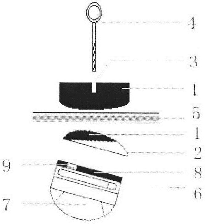
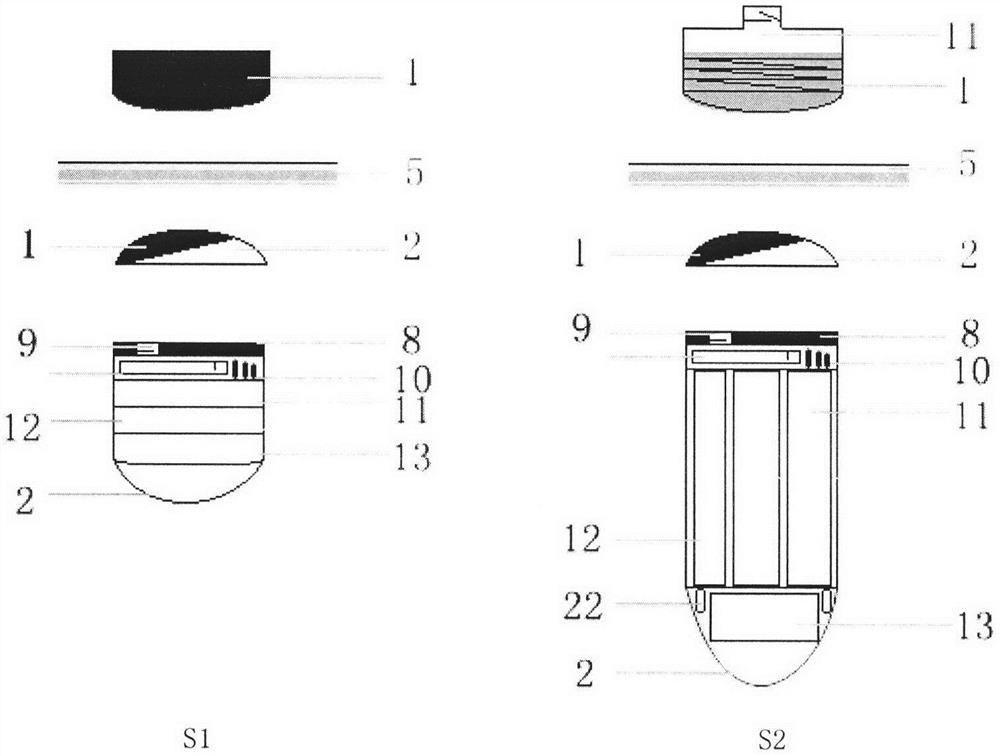
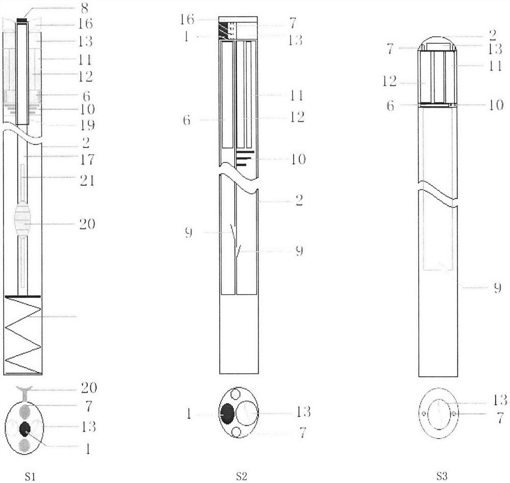
[0048] 1. Magnet 2. Shell 3. Nut socket 4. Traction bolt 5. Anterior abdominal wall

[0049] 6. Battery 7. Lamp 8. Iron sheet 9. Switch 10. Antenna

[0050] 11. RF transmitter module 12. Image processing module 13. Lens

[0051] 14. Abdominal wall sheath tube 15. Sheath tube 16. Transparent body 17. Take-out rod 18. Spring 19. Inner sheath 20. Pull button 21. Push groove 22. LED light

[0052] 23. Traction frame 24. Traction rope 25. Bed board 26. High-energy magnet 27. Lifting device 28. Support table

[0053] as attached figure 1 , attached figure 2 As shown, the built-in part and the external part of the magnetic control mounting device of the wireless device are both disc-like monomers, and the magnet 1 adopts a rare-earth permanent magnet and is seal...


PUM


Abstract

The invention provides a wireless laparoscope system and a using method thereof. An operating lamp and a camera are in wireless micro design, are adsorbed on a magnetic control device, are fed into an abdominal cavity through an abdominal wall sheathing canal by a wireless visual magnetic control taking and feeding device, and are adsorbed on a peritoneal surface of an anterior abdominal wall in a magnetic control mode at a proper angle; and images in the abdominal cavity are transmitted to in-vitro video terminals such as a mobile phone, a computer and an intelligent display screen in a wireless signal mode, and examination and operation in the abdominal cavity are performed, namely the wireless laparoscope is obtained. The invention further provides a handheld wireless laparoscope and a magnetic control pneumoperitoneum-free laparoscope space system. The defects of a laparoscope holding hand, a two-dimensional visual field and the like during the existing laparoscopic surgery are overcome, the shadowless and three-dimensional visual field is returned under the laparoscopic surgery, the obstruction of a hard laparoscope and a cable thereof is eliminated, the chopstick effect of mutual collision and shielding among surgical instruments is reduced, the equipment is simplified, the surgical manpower is released, the possibility of the individual laparoscopic surgery is improved, the efficiency of application, training and popularization is high, and the development of the laparoscopic surgery towards the aesthetic recovery of ultramicro wounds is effectively promoted.

Description

technical field [0001] The invention relates to a set of wireless laparoscopic system and using method, which are used for abdominal examination and operation, and relate to the technical field of medical instruments. Background technique [0002] Using a shadowless lamp and looking directly at the naked eye are the characteristics of traditional abdominal open surgery. The linearity of the light and line of sight restricts the degree of freedom of surgery. mouth to make up for. [0003] Laparoscopic surgery consisting of an insufflation machine, cold light source optical fiber, camera imaging system and digital TV has significantly changed the above-mentioned deficiencies. Lighting is transmitted to the abdomen through optical fiber cables; intra-abdominal images are displayed on the TV screen through the camera and video connection. , the above-mentioned crowding effect of light and line of sight is changed in the form of cables, and the surgical incision is changed from ...

Claims


Application Information

Patent Timeline
IPC IPC(8): A61B1/313A61B1/00A61B1/045A61B1/05A61B1/06A61B17/00A61B17/02
CPCA61B1/3132A61B1/00016A61B1/00045A61B1/00071A61B1/00158A61B1/05A61B1/0684A61B1/045A61B17/0218A61B17/0281A61B17/00234A61B2017/003
Inventor 伍端友
Owner 伍端友
Why Eureka
Try Eureka