
Polishing and deburring device

A deburring and charging technology, which is applied in the direction of abrasive feeding device, used abrasive processing device, separation method, etc., can solve the problems of high labor intensity of workers, impurities blocking pipelines, environmental pollution, etc., to prevent Excessive friction and workpiece scratches, ensuring stable movement, and easy lubrication

Pending Publication Date: 2021-05-25
CHANGSHA AERONAUTICAL VACATIONAL AND TECHNICAL COLLEGE
View PDF0 Cites 4 Cited by
  • Summary
  • Abstract
  • Description
  • Claims
  • Application Information

AI Technical Summary

Problems solved by technology

[0002] At present, it is difficult to process shell parts using traditional finishing technology. The surface finishing of some special-shaped parts and the surface of inner and outer circular parts with various small grooves is generally done by manual methods, and the labor intensity of workers is very high. Large, and serious environmental pollution, the vibration deburring system has a wide range of applications and good processing effects, especially suitable for deburring the surface of parts after machining or molding processes
[0003] However, the existing vibration deburring system has the following problems: 1. Due to the limitation of equipment installation space, the components of the equipment are interfered, resulting in a decrease in vibration effect and processing effect; 2. Lack of oil purification structure or poor oil purification effect OK, causing impurities to clog the lines

Method used


Image

  • Polishing and deburring device
  • Polishing and deburring device

Examples


Embodiment

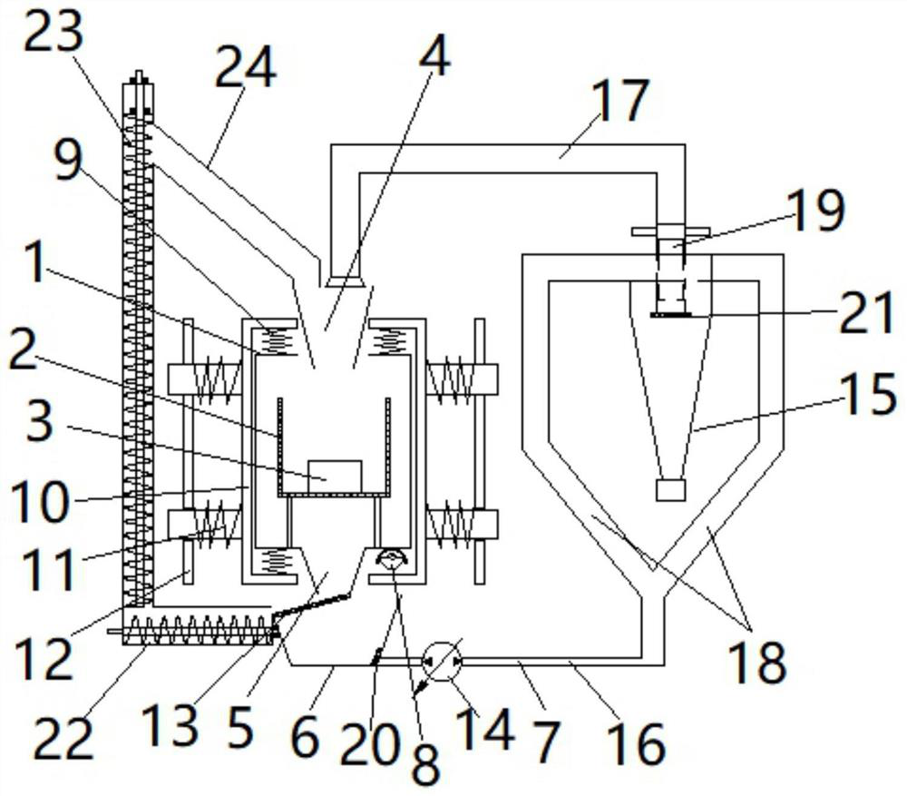
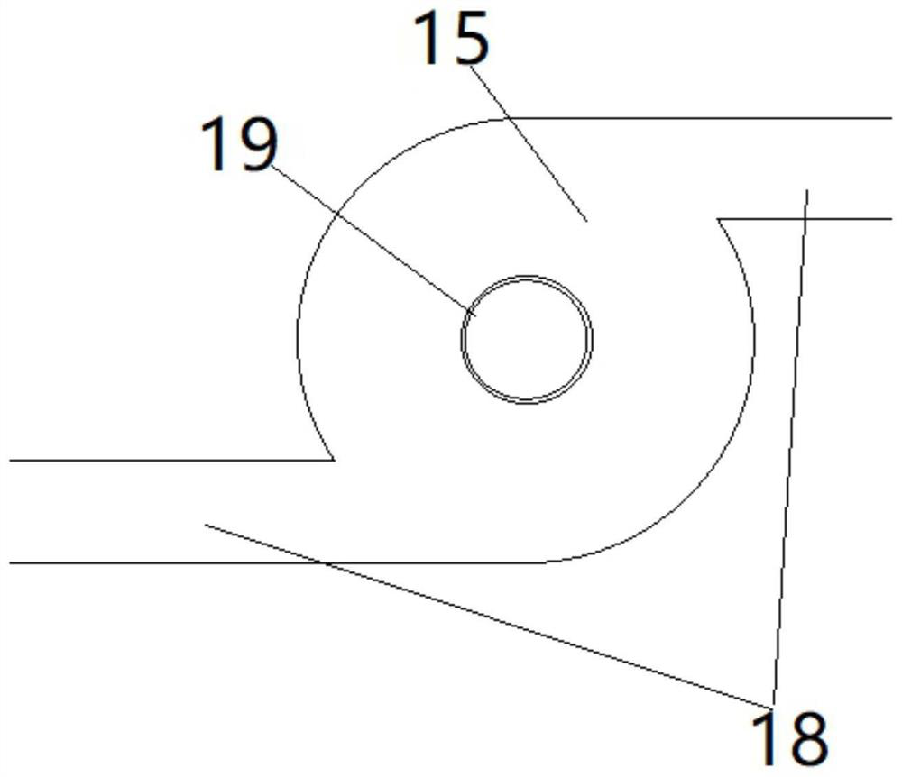
[0035] A polishing and deburring device, including a working chamber 1, a conveying assembly, an oil tank mechanism, a first moving assembly, a second moving assembly and a limit assembly, such as Figure 1-2 As shown, the details are as follows:

[0036] Such as figure 1As shown, the shape of the working room is a rectangular box, and the loading basket 2 (the workpiece 3 is arranged in the charging basket) is supported in the inside of the working room by a support rod; and the upper and lower ends of the working room are correspondingly provided with feeding ports 4 and outlet 5, the loading basket corresponds to the direction in which the abrasive material falls along the material inlet and outlet, and the abrasive material falls into the loading basket from the material inlet, and moves (vibrates) through the working room so that the abrasive material and the workpiece are fully contact to realize the grinding and polishing of the workpiece; there is a mesh on the loadin...


PUM


Abstract

The invention discloses a polishing and deburring device. The polishing and deburring device comprises a working chamber, a conveying assembly, an oil tank mechanism, a first movement assembly, a second movement assembly and a limiting assembly. The working chamber is driven by an eccentric wheel to swing, so that a workpiece is ground and polished by an abrasive material; through buffering andresetting of a first elastic piece, the abrasive material can make full contact with the workpiece conveniently, and the surface wall of the workpiece is effectively polished; the limiting assembly can guarantee that a frame reciprocates in the horizontal direction; through arrangement of a second elastic piece, the frame is buffered and reset; the first elastic piece is arranged between the frame and the working chamber, the second elastic piece is arranged between a positioning plate and the frame, and thus interference between the first elastic piece and the second elastic piece can be effectively avoided; through the oil tank mechanism, lubrication between the abrasive material and the workpiece is facilitated, and excessive friction and scratching of the workpiece are prevented; and the abrasive material at a discharging outlet can be conveyed to a feeding inlet through the conveying assembly by a conveying mechanism, the abrasive material circulates in the working chamber, and the practicability is good.

Description

technical field [0001] The invention relates to the technical field of polishing and grinding, in particular to a polishing and deburring device. Background technique [0002] At present, it is difficult to process shell parts using traditional finishing technology. The surface finishing of some special-shaped parts and the surface of inner and outer circular parts with various small grooves is generally done by manual methods, and the labor intensity of workers is very high. Large, and serious environmental pollution, the vibration deburring system has a wide range of applications and good processing effects, especially suitable for deburring the surface of parts after machining or forming processes. [0003] However, the existing vibration deburring system has the following problems: 1. Due to the limitation of equipment installation space, the components of the equipment are interfered, resulting in a decrease in vibration effect and processing effect; 2. Lack of oil puri...

Claims


Application Information

Patent Timeline
Patent Type & Authority Applications(China)
IPC IPC(8): B24C1/08B24C3/04B24C7/00B24C9/00B01D36/02
CPCB01D36/02B24C1/083B24C3/04B24C7/0007B24C9/00B24C9/006
Inventor 沈宇峰杨丰何幸保唐军
Owner CHANGSHA AERONAUTICAL VACATIONAL AND TECHNICAL COLLEGE
Learn More