

Postweld heat treatment method for blast furnace five-way ball
A post-weld heat treatment, five-way ball technology, used in heat treatment furnaces, heat treatment equipment, heat treatment process control and other directions
- Summary
- Abstract
- Description
- Claims
- Application Information
AI Technical Summary
Problems solved by technology
Method used
Image

Examples
Embodiment Construction
[0017] A post-welding heat treatment method for blast furnace five-way balls, comprising the steps of:
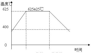
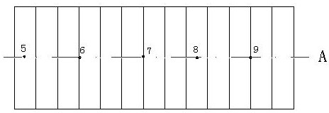
[0018] First of all, place the test board in the temperate zone and place three test boards at intervals of 120° for synchronization. Set the temperature measuring point on the test board and thicken the insulation layer here to ensure that the temperature of the test board is the same as that of the spherical shell plate;
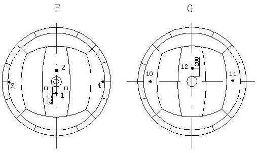
[0019] Secondly, before heat treatment, two holes with a size of not less than φ500 are opened in the spherical shell, and the opening positions at the position of the ascending pipe and the position of the descending pipe are selected, one for each place, as the air inlet and smoke exhaust port of the burner nozzle;
[0020] One of the openings must be placed at a lower position from the ground to facilitate the placement of heat treatment equipment during heat treatment, and the other as a smoke exhaust port, placed far away from flammable and explosiv...
PUM
 Abstract
Description
Claims
Application Information