Efficient vacuum heat pipe heat collector

A technology of vacuum heat pipes and heat collectors, which is applied to solar heat collectors, working fluids of solar heat collectors, solar heat collectors using working fluids, etc. and other problems, to achieve the effect of increasing the heating surface area, accelerating evaporation and vaporization, and improving heating efficiency

Pending Publication Date: 2021-05-25
赣州能创智能科技有限公司
View PDF12 Cites 0 Cited by
  • Summary
  • Abstract
  • Description
  • Claims
  • Application Information

AI Technical Summary

Problems solved by technology

[0003] However, there are still some deficiencies in the existing heat pipe vacuum tube collectors in actual use: First, because the existing solar heat pipe vacuum tube collectors all use liquid inorganic heat transfer fluid, and there is an inclination angle when the collectors are installed. , all heat transfer working fluids are often concentrated at the lower end of the heat pipe, which not only results in a small evaporation surface area of ​​the heat transfer working fluid, which is not conducive to rapid heat absorption and evaporation, but also has a large contact area between the liquid working fluid and the backside of the heat pipe, and contacts with the sunny side of the heat pipe. The area is small, and when the solar tube collects heat, the su

Method used


Image

  • Efficient vacuum heat pipe heat collector
  • Efficient vacuum heat pipe heat collector
  • Efficient vacuum heat pipe heat collector

Examples


Embodiment Construction

[0023] The following will clearly and completely describe the technical solutions in the embodiments of the present invention with reference to the accompanying drawings in the embodiments of the present invention. Obviously, the described embodiments are only some, not all, embodiments of the present invention. Based on the embodiments of the present invention, all other embodiments obtained by persons of ordinary skill in the art without making creative efforts belong to the protection scope of the present invention.

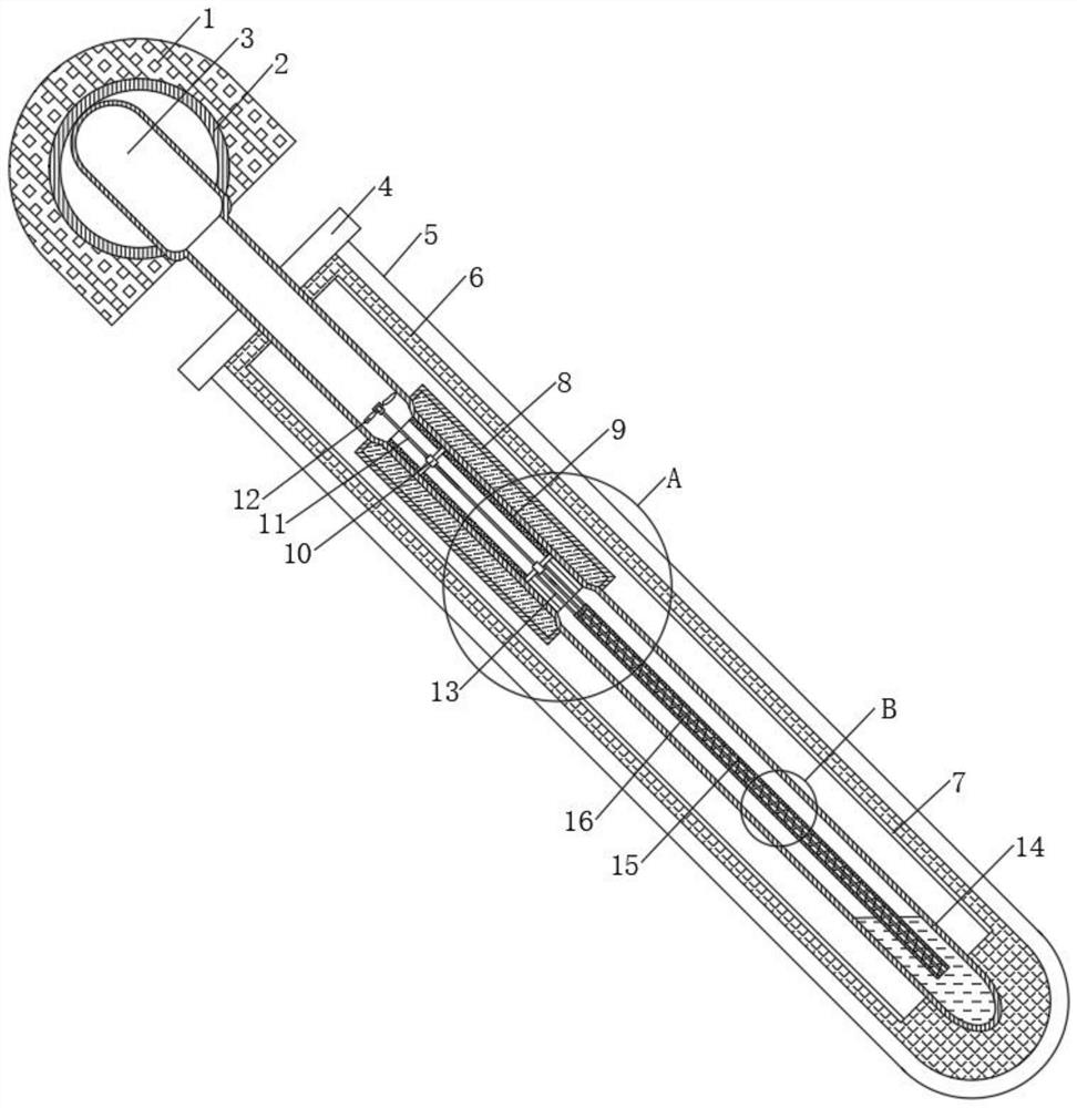
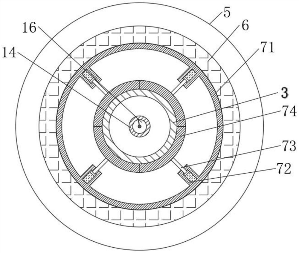
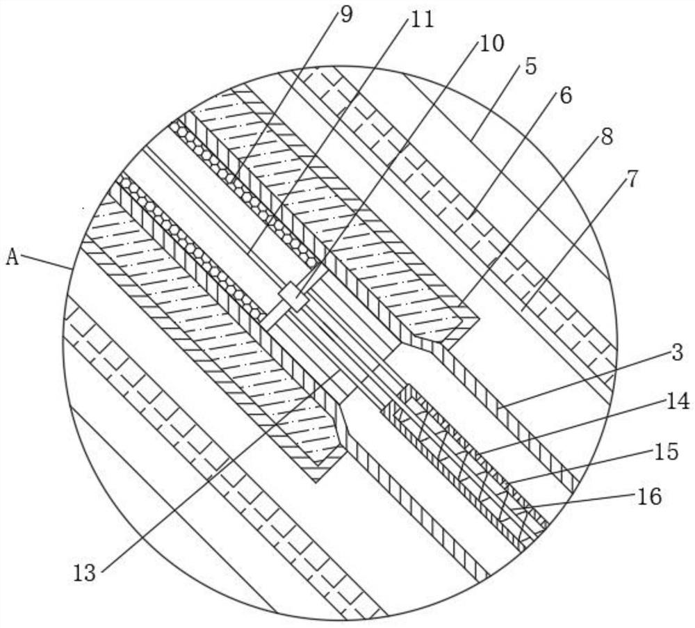
[0024] see Figure 1-4 , a high-efficiency vacuum heat pipe heat collector, comprising an insulation layer 1, the inside of the insulation layer 1 is fixedly connected with a header 2, the inside of the header 2 is fixedly connected with a heat pipe 3, and the upper part of the heat pipe 3 is fixedly connected with a fixed ring 4 The outer side of the bottom of the fixed ring 4 is fixedly connected with a vacuum glass tube 5, the inner side of the vacuum glass...


PUM


Abstract

The invention relates to the technical field of photovoltaic heat energy, and discloses an efficient vacuum heat pipe heat collector. The efficient vacuum heat pipe heat collector comprises a heat preservation layer, wherein a union pipe is fixedly connected to the interior of the heat preservation layer, a heat pipe is fixedly connected to the interior of the union pipe, a fixing ring is fixedly connected to the upper portion of the heat pipe, and a vacuum glass pipe is fixedly connected to the outer side of the bottom of the fixing ring. Through the arrangement of an impeller, an auger and a through hole, when a heat collecting energy pipe is irradiated by sunlight, a heat transfer medium in the heat pipe is heated, evaporated and vaporized, steam rises and is blown to the impeller, the rotating impeller drives the auger to rotate, the heat transfer medium at the bottom is pumped to the upper portion of an upper water barrel, the heat transfer medium is sprayed out from the through hole under the action of liquid pressure, the heat transfer medium is sprayed to the sunny slope of the heat pipe, namely the highest-temperature portion of the heat pipe, evaporation and vaporization of the heat transfer medium can be accelerated, the heated surface area of the heat transfer medium can be increased, evaporation and vaporization of the heat transfer medium are further accelerated, and the heating efficiency of the vacuum heat pipe heat collector is greatly improved.

Description

technical field [0001] The invention relates to the technical field of photovoltaic thermal energy, in particular to a high-efficiency vacuum heat pipe heat collector. Background technique [0002] The heat pipe vacuum tube solar collector is a kind of water-passing solar collector that uses the heat pipe vacuum heat collector tube to absorb solar radiation energy, uses inorganic heat transfer medium as the heat transfer medium, and then heats the water in the header pipe or the water tank. device. The basic working principle of the heat pipe vacuum tube solar collector is as follows: sunlight passes through the heat collecting tube and irradiates on the selective absorption film of the inner tube of the heat collecting tube. To the built-in heat pipe, quickly heat and vaporize the working medium in the evaporation section of the heat pipe, and the vaporized substance rises to the condensation section of the heat pipe, so that the temperature of the condensation section ris...

Claims


Application Information

Patent Timeline
IPC IPC(8): F24S10/95F24S80/10F24S80/20F28D15/02
CPCF24S10/95F24S80/10F24S80/20F28D15/02Y02E10/44
Inventor 不公告发明人
Owner 赣州能创智能科技有限公司
Why Eureka
Try Eureka