A Waste Heat Furnace with Adjustable Injection of Urea to Remove Fly Ash

A waste heat furnace, adjustable technology, applied in the direction of incinerators, lighting and heating equipment, emission prevention, etc., can solve the problems of limited ash cleaning efficiency, heat waste, increase in boiler exhaust temperature, etc., to ensure denitrification effect and avoid smoke The effect of air escaping and prolonging the service life

Active Publication Date: 2021-10-22
上海域德环保股份有限公司
View PDF0 Cites 0 Cited by
  • Summary
  • Abstract
  • Description
  • Claims
  • Application Information

AI Technical Summary

Problems solved by technology

When the flue gas flows through the cavity of the membrane wall, the dust in the flue gas will accumulate on the surface of the membrane wall, and as the running time increases, the deposited fly ash will gradually thicken, which will greatly reduce the heat transfer effect of the tube and reduce the temperature of the boiler. The heat exchange efficiency increases, the boiler exhaust temperature increases, resulting in waste of heat, and at the same time the boiler steam output decreases, reducing the benefits of the enterprise
The usual cleaning methods include vibration cleaning and shock wave cleaning. The structure of the membrane wall boiler is very strong, and vibration cleaning has no obvious effect. Due to the large volume of the cavity, the shock cleaning efficiency is low. It is also very limited. In addition, the flue gas from hazardous waste incineration is relatively viscous, and the fly ash has a certain viscosity, which increases the difficulty of ash cleaning. It is a common problem that the ash accumulation in hazardous waste incineration boilers is difficult to clean.

Method used


Image

  • A Waste Heat Furnace with Adjustable Injection of Urea to Remove Fly Ash
  • A Waste Heat Furnace with Adjustable Injection of Urea to Remove Fly Ash
  • A Waste Heat Furnace with Adjustable Injection of Urea to Remove Fly Ash

Examples


Embodiment Construction

[0031] The following will clearly and completely describe the technical solutions in the embodiments of the present invention with reference to the accompanying drawings in the embodiments of the present invention. Obviously, the described embodiments are only some, not all, embodiments of the present invention. Based on the embodiments of the present invention, all other embodiments obtained by persons of ordinary skill in the art without making creative efforts belong to the protection scope of the present invention.

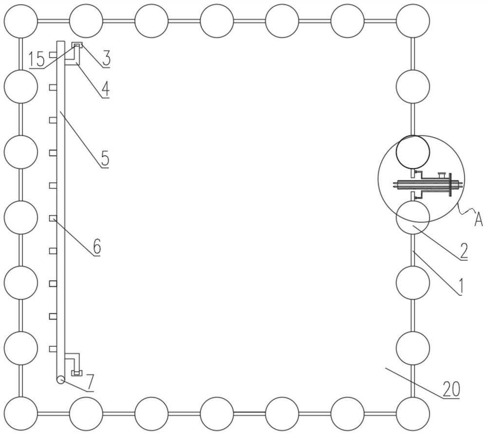
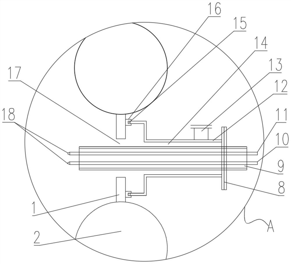
[0032] see Figure 1-4 , the present invention provides a technical solution: as figure 1 and figure 2 , a waste heat furnace capable of removing fly ash with adjustable injection of urea, comprising a waste heat furnace body 20, the waste heat furnace body 20 including several boiler membrane wall tubes 2 and a boiler located between two adjacent boiler membrane wall tubes 2 Membrane wall fins 1, boiler membrane wall fins 1 are provided with openings 17, a...


PUM


Abstract

The invention discloses a waste heat furnace capable of removing fly ash with adjustable injection of urea, which comprises a waste heat furnace body, and the waste heat furnace body includes several boiler membrane wall tubes and a boiler membrane wall tube located between two adjacent boiler membrane wall tubes. Boiler membrane wall fins, the boiler membrane wall fins are provided with openings, and the outer side of the waste heat furnace body is provided with a dual-fluid spray gun, and the end of the dual-fluid spray gun close to the nozzle runs through the opening, and the inside of the dual-fluid spray gun A compressed air atomization pipeline and a urea solution pipeline are provided, and the compressed air atomization pipeline and the urea solution pipeline are connected to each other, and several temperature measurement points are arranged in the waste heat furnace body, and the two-fluid spray gun according to the temperature measurement The temperature of the point moves up and down; the invention can adjust the injection of urea and remove the fly ash in the furnace.

Description

technical field [0001] The invention relates to the technical field of waste treatment machinery, in particular to a waste heat furnace capable of removing fly ash by adjustable injection of urea. Background technique [0002] Since hazardous waste contains nitrogen and the standard requires that the combustion temperature of the second combustion chamber stay at 1100°C for no less than 2 seconds, the nitrogen in the waste and the nitrogen in the combustion-supporting air will produce nitrogen oxides during high-temperature combustion. There are emission limit requirements for the emission value of nitrogen oxides in the norms, and the emission cannot exceed the standard. For this reason, it is necessary to spray urea solution near the boiler inlet position (flue gas temperature is 950°C), and the sprayed urea solution reacts with nitrogen oxides in the flue gas, thereby reducing nitrogen oxides to nitrogen and water, and as a flue gas. The composition of the gas is emitted...

Claims


Application Information

Patent Timeline
Patent Type & Authority Patents(China)
IPC IPC(8): F23G5/44F23G5/46F23G5/50F23J1/00F23J15/00B01D53/79B01D53/56B01D53/34
CPCB01D53/346B01D53/56B01D53/79B01D2251/2067B01D2258/0283F23G5/44F23G5/46F23G5/50F23J1/00F23J15/003F23J2215/10
Inventor 乔德友陶经坚朱海滨程强祥杨晓磊方鹏程
Owner 上海域德环保股份有限公司
Why Eureka
Try Eureka