Thermal barrier coating interface cracking prediction method

A technology of thermal barrier coatings and prediction methods, applied in special data processing applications, instruments, electrical digital data processing, etc., can solve the problems of shortening the safe service life of gas turbines and aggravating the failure and damage of thermal barrier coatings

Pending Publication Date: 2021-05-28
FUZHOU UNIV
View PDF2 Cites 0 Cited by
  • Summary
  • Abstract
  • Description
  • Claims
  • Application Information

AI Technical Summary

Problems solved by technology

Under the extremely high temperature working environment, the failure and damage of the thermal barrier coating is exacerbated, which greatly shortens the safe service

Method used


Image

  • Thermal barrier coating interface cracking prediction method
  • Thermal barrier coating interface cracking prediction method
  • Thermal barrier coating interface cracking prediction method

Examples


Embodiment Construction

[0031] The present invention will be further described below in conjunction with the accompanying drawings and embodiments.

[0032] The invention provides a method for predicting interface cracking of a thermal barrier coating, comprising the following steps:

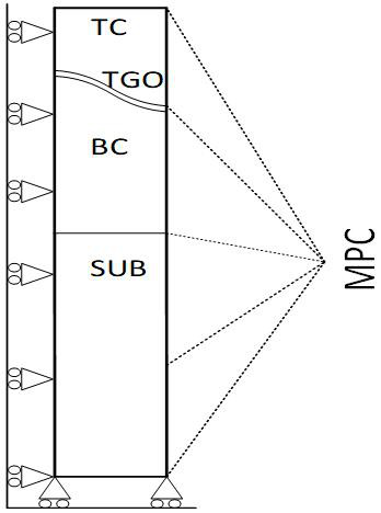
[0033] Step S1: constructing a two-dimensional geometric model of the thermal barrier coating, the model includes a ceramic layer TC, an oxide layer TGO, a bonding layer BC, and a nickel-based alloy substrate SUB;

[0034] In this example, if figure 1 As shown, the TBCs geometric model of the two-dimensional thermal barrier coating system is established using ABAQUS software. The TBCs model includes the ceramic layer TC, the oxide layer TGO, the bonding layer BC, and the nickel-based alloy substrate SUB. In order to characterize the unevenness of the internal interface of the coating The morphology of the TGO layer is divided by sinusoidal curves on both sides of the interface.

[0035] Step S2: Mesh the established ...


PUM


Abstract

The invention relates to a thermal barrier coating interface cracking prediction method. The method comprises the following steps: S1, constructing a two-dimensional geometric model of the thermal barrier coating; s2, dividing grids, and inserting cohesion units in TGO/TC and TGO/BC interfaces; s3, setting parameters of the TC layer, the TGO layer, the BC layer and the SUB layer respectively, and adding damage parameters to TGO/TC and TGO/BC interface cohesion units; s4, assembling the two-dimensional geometric model of the thermal barrier coating, and setting the thermal cycle load time of the viscosity analysis step as T; s5, applying a symmetric boundary condition to the left side of the thermal barrier coating two-dimensional geometric model, applying a periodic boundary condition MPC multi-point coupling constraint condition to the right side of the thermal barrier coating two-dimensional geometric model, and constraining the y-direction freedom degree at the bottom; s6, applying a thermal cycle load of the analysis step through a self-defined amplitude curve; and S7, circulating the step S6 to complete a preset number of thermal load cycles to obtain a cracking prediction result of the two-dimensional geometric model of the thermal barrier coating. The method can effectively predict the nucleation position and the expansion condition of the interface crack of the thermal barrier coating.

Description

technical field [0001] The invention relates to the field of thermal barrier coatings, in particular to a method for predicting interface cracking of thermal barrier coatings. Background technique [0002] Gas turbines are an important pillar of the modern aviation industry and a symbol of the country's major equipment manufacturing level. Thermal barrier coating technology is one of the core technologies for the development of advanced heavy-duty gas turbines. It covers the surface of the turbine substrate with a layer of thermal insulation material with low thermal conductivity and high stability. It not only has a thermal barrier effect, but also prevents oxidation and corrosion. And damage to the blade caused by foreign matter erosion. At present, the gas temperature of F-class heavy-duty gas turbines has reached 1400°C, and the gas temperature of heavy-duty gas turbines will exceed 1700°C in the future. Under the extremely high temperature working environment, the fai...

Claims


Application Information

Patent Timeline
IPC IPC(8): G06F30/23G06F119/08G06F119/14
CPCG06F30/23G06F2119/08G06F2119/14
Inventor 钟舜聪李佐君梁伟
Owner FUZHOU UNIV
Why Eureka
Try Eureka