Network cable processing equipment

A technology for processing equipment and network cables, which is applied to equipment for dismantling/armoring cables, cable installation devices, recycling technology, etc. It can solve the problems of difficult processing, waste of resources, and poor practicability, and improve processing efficiency. , the effect of reducing power loss and improving practicability

Active Publication Date: 2021-05-28
杭州临安锦金线缆有限公司
View PDF9 Cites 0 Cited by
  • Summary
  • Abstract
  • Description
  • Claims
  • Application Information

AI Technical Summary

Problems solved by technology

[0002] A certain amount of waste will be generated during the production, processing and use of the network cable. If it is discarded, it will seriously pollute the environment and waste a lot of resources; but because the network cable is thin and has multiple core wires inside, it is difficult to peel and recycle.
When the existing network cable processing equipment peels the network cable, the rubber sheath of the network cable is discharged together with the battery core of the network cable, which leads to the subsequent staff needing to manually separate the rubber sheath and the battery core, which makes the processing difficult , low work efficiency; and in the prior art, some stripping devices for network cables cannot classify and recycle battery cells and rubber sheaths, which cannot meet the needs of social development, and some network cable processing devices only cut and grind the rubber sheaths , leading to the production of a large amount of harmful substances, and the subsequent processing costs increase, resulting in poor practicability

Method used


Image

  • Network cable processing equipment
  • Network cable processing equipment
  • Network cable processing equipment

Examples


Embodiment 1

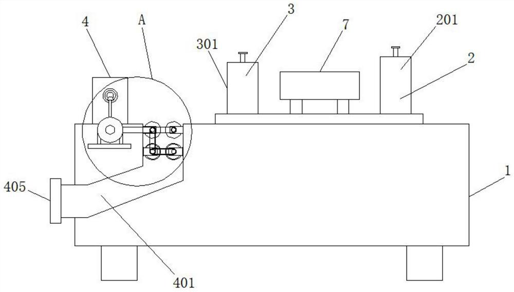
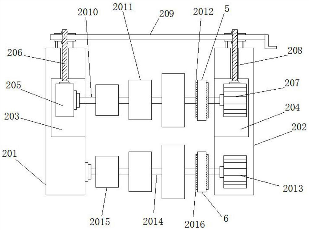
[0026] see Figure 1-7, a network cable processing equipment, including a base 1, the top of the base 1 is sequentially installed with a wire inlet mechanism 2, a peeling mechanism 3 and a recovery mechanism 4, and the wire inlet mechanism 2 includes a No. 1 fixed on the top of the base 1 Support plate 201 and No. 2 support plate 202, and the opposite sides of No. 1 support plate 201 and No. 2 support plate 202 are respectively provided with No. 1 movable groove 203 and No. 2 movable groove 204, and the inside of No. 1 movable groove 203 is slidingly connected with sliding Block 205, and the top of slide block 205 is connected with No. 1 threaded rod 206 through bearing rotation, and the inside of No. 2 movable groove 204 is connected with No. 1 motor 207 slidingly, and the top of No. 1 motor 207 is connected with No. 2 threaded rod 208 through bearing rotation One end of No. 1 threaded rod 206 and one end of No. 2 threaded rod 208 are threadedly connected with No. 3 threaded ...

Embodiment 2

[0031] On the basis of Example 1, please refer to Figure 1-7 :

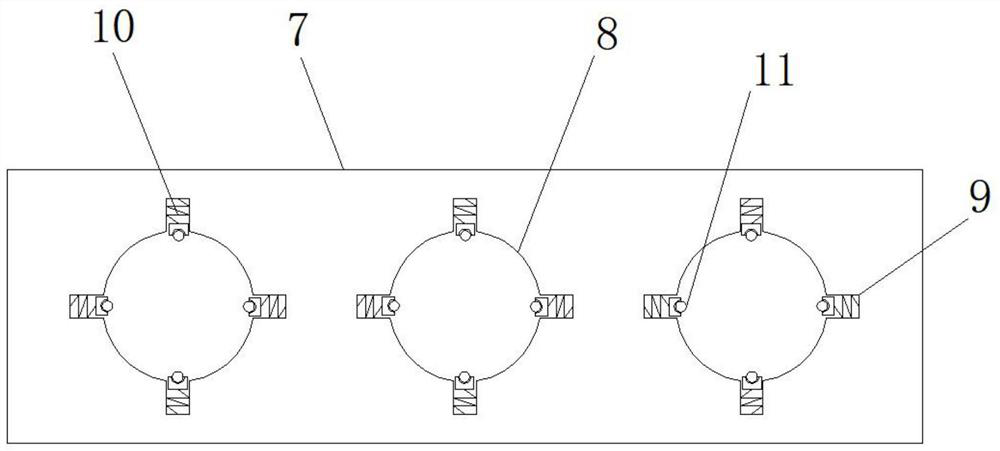
[0032] Concrete, between the wire inlet mechanism 2 and the peeling mechanism 3, a lead plate 7 is horizontally arranged, and the surface of the lead plate 7 is provided with several guide grooves 8, and the inner walls of some guide grooves 8 are all provided with some grooves 9, and the grooves The inside of 9 is fixedly connected with spring 10, and the other end of spring 10 is fixedly connected with pulley 11, and pulley 11 is in contact with the outer wall of network cable, can reduce the friction of network cable and guide groove 8 inside, is convenient to network cable moves.

[0033] Specifically, the pulley 11 forms an elastic stretch structure through the spring 10 and the groove 9, which is convenient for transporting network cables of different sizes.

[0034] In this embodiment, one end of the network cable enters the guide groove 8 on one side of the wire guide plate 7, and under the action of th...

Embodiment 3

[0036] On the basis of Example 1, please refer to Figure 1-7 :

[0037] Specifically, the winding device 406 is composed of a No. 1 base 4061, a No. 2 base 4062, and a winding roller 4063. Both the No. 1 base 4061 and the No. 2 base 4062 are horizontally sleeved with a connecting rod 4064, and the winding roller Both ends of 4063 are fixed with connecting rod 4064 by bolts, the other end of connecting rod 4064 is fixedly connected with No. 1 rotating rod 4065, the top of base 1 is provided with adjustment groove 4066, and the bottom end of No. 1 base 4061 is fixedly connected with adjusting block 4067, one end of the No. 1 rotating rod 4065 is fixedly connected with the No. 1 connecting gear 4068, and the outer wall of the No. 1 connecting gear 4068 is engaged with the No. 2 connecting gear 4069, and one end of the No. 2 connecting gear 4069 is fixedly connected with the No. 2 rotating rod 4610. And the other end of the No. 2 rotating rod 4610 is fixedly connected with the N...


PUM


Abstract

A network cable processing device disclosed by the present invention comprises a base, the top end of the base is sequentially provided with a cable inlet mechanism, a peeling mechanism and a recovery mechanism from right to left, and the cable inlet mechanism comprises a first support plate and a second support plate which are fixed at the top end of the base. A first movable groove and a second movable groove are formed in the opposite sides of the first supporting plate and the second supporting plate correspondingly, a sliding block is slidably connected to the interior of the first movable groove, a first threaded rod is rotatably connected to the top end of the sliding block through a bearing, and a first motor is slidably connected to the interior of the second movable groove; and the top end of the first motor is rotationally connected with a second threaded rod through a bearing, one end of the first threaded rod and one end of the second threaded rod are both in threaded connection with third threaded rods, and the output end of the first motor is fixedly connected with a first rotating shaft. According to the invention, network cables of different sizes can be efficiently peeled, and rubber sheaths of the network cables of different sizes and battery cells of the network cables can be effectively classified and recycled.

Description

technical field [0001] The invention relates to the field of network cable processing equipment, in particular to network cable processing equipment. Background technique [0002] A certain amount of waste will be generated during the production, processing and use of the network cable. If it is discarded, it will seriously pollute the environment and waste a lot of resources; but because the network cable is thin and has multiple core wires inside, it is difficult to peel and recycle. When the existing network cable processing equipment peels the network cable, the rubber sheath of the network cable is discharged together with the battery core of the network cable, which leads to the subsequent staff needing to manually separate the rubber sheath and the battery core, which makes the processing difficult , low work efficiency; and in the prior art, some stripping devices for network cables cannot classify and recycle battery cells and rubber sheaths, which cannot meet the n...

Claims


Application Information

Patent Timeline
Patent Type & Authority Applications(China)
IPC IPC(8): H02G1/12H01B15/00
CPCH02G1/126H01B15/00H01B15/006Y02W30/82
Inventor 黄跃跟
Owner 杭州临安锦金线缆有限公司
Why Eureka
Try Eureka